The eccentric wheel.
 |
| The eccentric wheel. |
|---|
I found this picture years ago on a website that is now dead. I removed distractions from it, reducing it to its simplest form.
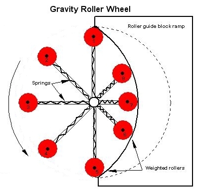
A wheel has 8 weighted rollers (red) on eight spokes, each with a spring inside. The rollers on the left are at their maximum extension. On the right the rollers are constrained by the heavy fixed block with a curved wall (segment of a circle). The springs keep the rollers at their maximum extent on the left side. The wall forces them toward the axle. Clearly there is no mass unbalance with respect to the axle (always four rollers on each side of the axle). The inventor says that the gravitational torques on the weighted rollers are continually unbalanced, being greater on the left side, resulting in continual counter-clockwise rotation (shown by an arrow).
Comments: To satisfy the conditions of equilibrium, the system must not only have a net force of zero and a net torque of zero acting on it, but also be properly held or constrained on its supports. The more stable the supports the more stable is the equilibrium, that is the equilibrium is achived more easily. If the system has continual torque imbalance, why can't it turn continually?
Solution.
The rotatable system does not have torque imbalance. Several observations all lead to that conclusion.Of course we see that as the wheel is turned, every roller gains the same potential energy on one side as it loses on the other during a full rotation. I said "is turned" not "turns", for it won't turn by itself. Case closed.
We also see that rotation of the wheel by 1/8 turn gives the very same configuration, so it won't make that move by itself. Again, case closed.
But the most basic reason this won't work has to do with a fundamental principle of physics—the definition of work. Work is defined to be W = F•s, the scalar product of the vector force and vector displacement. Equivalently it is W = Fs(cosθ) where θ is the angle between F and s. When two objects are in contact they exert forces on each other that are perpendicular to the tangent of the surfaces at the point of contact. Therefore the motion of one body sliding on another is always in the direction of this tangent. The force at the contact point is perpendicular to the displacement and zero work is done by this force. No work is done on or by bodies sliding along a frictionless unmoving surface.
The wall is a rigid, unmoving frictionless surface. It does no work on the rotatable system. This is true for any shape of wall.
Looking deeper.
The system has positions of equilibrium. If the picture shows one of them, there are seven more since rotation by 1/8 revolution looks the same. In the position shown the center of mass of the wheel is on a level line through the axle, and is to the left of the axle.Now imagine turning the wheel 1/16 revolution, so the rollers are between the positions shown. Where is the new center of mass? Take pairs of rollers on the same vertical. Their center of mass is at the same level as the axle. Add all pairs, and the center of mass of the system is again on the same level as the axle. Is it possible this cockeyed device has the same center of mass in all positions? If frictionless, then it would be equivalent to a frictionless flywheel. That's not what the inventor hoped.
Torques present an interesting slant on this, and are the final nail in its coffin. While the net torque on the rollers may be nonzero, this isn't the issue. We must look at the net torque on the entire rotatable system, and that curved wall exerts forces and torques on it.
If the curved wall weren't there, the springs and rollers would be extended to their limit and the system would be balanced in all positions. The net torque on the system would be zero. This is situation (A). Now put the curved wall in place and you have situation (B) shown in the diagram. What has changed? We have added forces of the ramp acting on the rollers. But these forces all have zero torque for they all pass through a common point. So the net torque on the wheel is still zero. Also, they are paired with equal and oppositely directed forces due to the springs. These are all internal forces in the system, and by Newton's third law such internal forces always sum to zero.
We use here an important fact about torques. We can choose any point as a center of torques, and if the net torque is zero about that point it will also be zero for any other point we choose. In this case we make our task easy by choosing the center of the wall's circular arc as the center of torques. Any force whose line of action passes through the center of torques has zero torque because its lever arm is zero.
This process for reaching this result was subtle, and perhaps devious. Here's an elaboration.What about the springs? They are irrelevant to our conclusion, for each spring compresses, then decompresses by the same amount when the wheel is rotated a full circle. Net work done: zero, assuming the springs are perfectly elastic, obeying Hooke's law. If the springs are not perfectly elastic, there will be dissipative heating of them, losing energy and slowing the wheel.Forces due to the circular arc of the curved wall on anything touching it are normal to the curve at the point of contact. So they will always be aimed toward the arc's center. When contacting some of the rollers, the net torque of the wall on those is zero. Suppose the wall is moved away, not touching any rollers. The sub-system of rollers is balanced in any position. If we slowly push the wall toward the rollers, touching them, we push them toward the axle. But due to the symmetry of the movable system about a horizontal line through the axle, each roller pushed higher is matched by one pushed lower by the same amount. The system's center of mass remains on that horizontal line through the axle. This fact holds as the wall is pushed closer, until it matches our drawing. Through the entire process the center of mass of the system niether rises or falls. The system shown in the drawing is still in eqilibirum, in any position of rotation. This process does not shift the center of mass of the wheel and roller sub-system.
In fact, this will be true for a wall of any shape that is symmetric about the horizontal line through the axle.
Also, the springs exert forces all passing through a common point, the axle, so they all exert zero torque on the system. The springs' forces are internal to the system and in a force analysis they add nothing to the net force on the system.
This analysis is overkill, but instructive. There's a whole class of unworkable perpetual motion proposals that use internal or external fixed constraints to move masses on a wheel as it is rotated. Similar analysis applies to them all.
Case finally closed for good.
Return to Physics puzzles.
Return to The Museum of Unworkable Devices.
Return to the Donald Simanek's home page.