 |
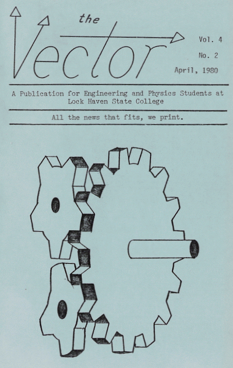
| The Vector Vol. 4, No. 2 April 1980. |
|---|
Illusory Gears:
A Breakthrough in
Mechanical Engineering.
by Donald E. Simanek.
The engineering draftsman has long been the unsung hero of mechanical engineering. It is his job to turn an engineer's ill-formed and half-baked ideas into neat drawings which a machinist can understand and convert into a working mechanism. Yet seldom does a draftsman get proper recognition. Never has a fundamental breakthrough been attributed to the humble draftsman.But now we can reveal to the scientific world just such a breakthrough. One of the perennial problems of gear design is "backlash" due to the slight looseness of fit where the teeth mesh. But tighter fits introduce faster wearing of the teeth, and that nemesis of engineers—friction.
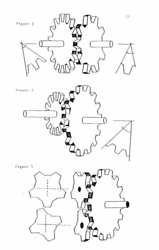
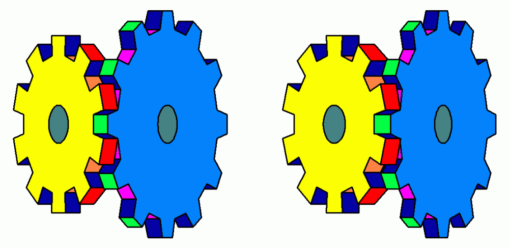
Now, with the aid of the deceptions of art, this problem has been solved. Figure 1. shows the basic principle. Perfectly intimate gear mating has been achieved. Look at the gear tooth (teeth?) where the gears mate. The tooth of the right-hand gear is at the same time the valley between the teeth of the left-hand gear. In fact, as gear teeth pass through this area they momentarily vanish, thus greatly reducing friction! In this primitive version of the principle, there do remain some problems with clearance of the gear teeth.
 |
| Evolution of the idea. |
|---|
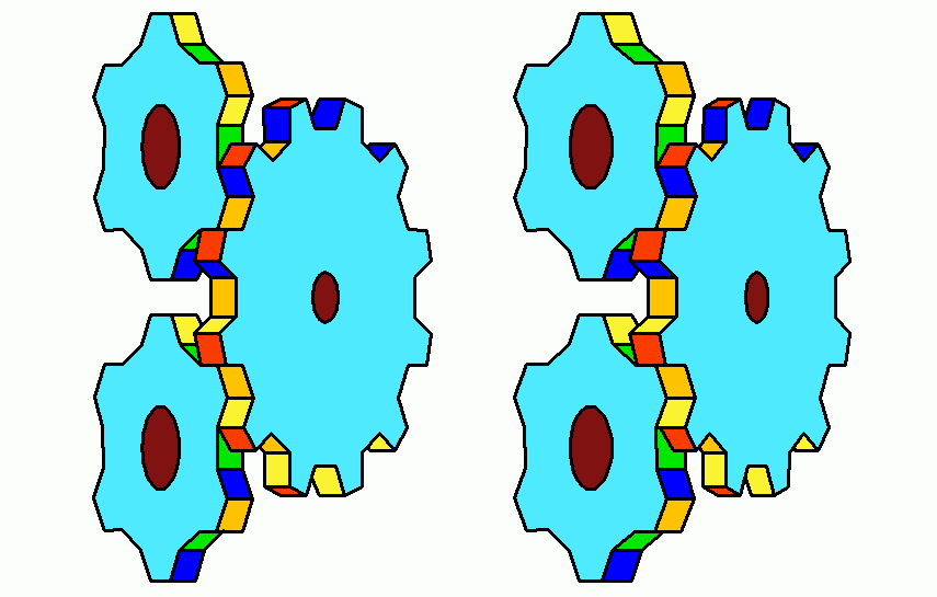
Figure 2 shows further evolution of the idea. This time the left gear has teeth of rather unorthodox shape. Also, we see that the two gear axles lie in different planes. This is a feat hard to achieve with traditional gear design. Still, there remain some clearance problems with the teeth.
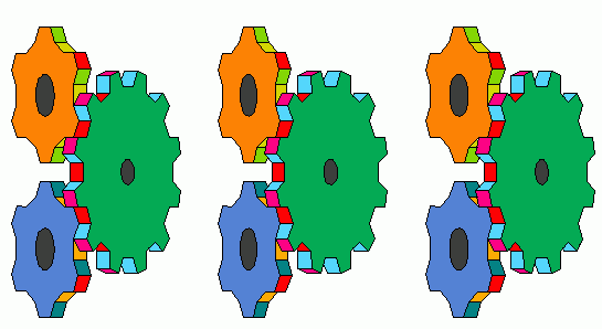
Figure 3 not only solves the clearance problem, but allows two small gears to be driven by one main gear, and all three gear axes lie in different planes.
Research continues. Figure 4 shows a prototype of a revolutionary ring gear. It has teeth on the inside and outside of the ring, but both inside and outside gear teeth are continues. The perceptive reader will observe that if about 1/3 of either end of the picture is covered, the remainder looks like a normal, old-fashioned, gear. Also note that as your gaze scans from left to right (or vice versa) the tops of gear teeth become valleys between teeth (and vice versa). Reverse your scan and they change the other way, but the change doesn't occur at the same place. This subtle shift of role from tops to valleys equalizes wear on the tooth surfaces when this gear is mated with other gears.
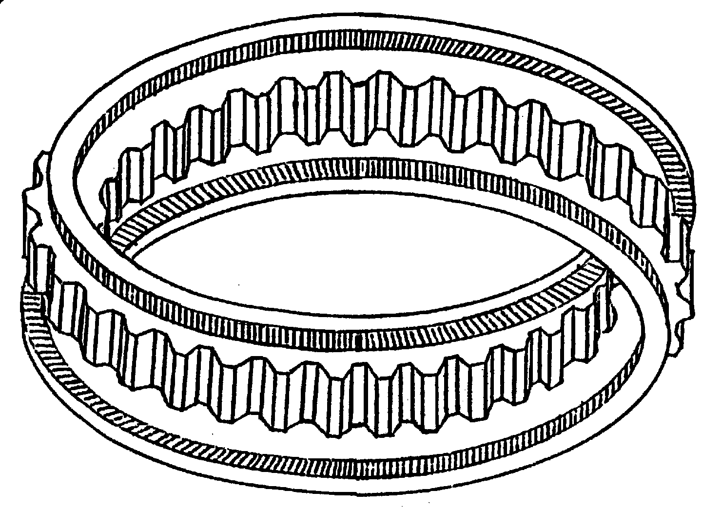 |
| Fig. 4. The revolutionary ring-gear. |
|---|
Truly these gears are a triumph of art over mundane reality. Research continues to design appropriate gear-cutting machhinery to produce them. Anyone desiring to manufacture these gears, or use them in any mechanism, may secure production rights from the inventor. Payment must be made in advance of production.
This article (above) with gear illusions, hand drawn, first appeared in The Vector Vol 4, No. 2. April 1980. All are © 1980 by Donald E. Simanek.
Now, with the aid of CAD computer software, better pictures of these gears may be rendered in color and 3d. All are © 2002 by Donald E. Simanek.
Color 3d pictures of the gear illusions.
[April, 2002] I finally got around to rendering my gear illusions in stereo. Where three images are shown, the left two are for parallel viewing, the right two for cross-viewing. When only two are shown, they are for cross-viewing. A crossview stereo pair for free-viewing can be much larger than one intended for parallel free-viewing.
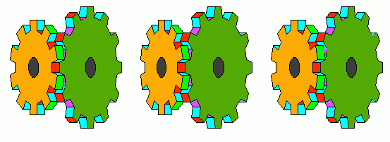
It's more dramatic when larger. Here's the version for cross-eyed viewing only.
Yet another gear illusion:
This gear illusion in 2D has been "ripped off" by several publishers without credit to me. As I was the originator of it, I'm the best person to explain it's logic.
 |
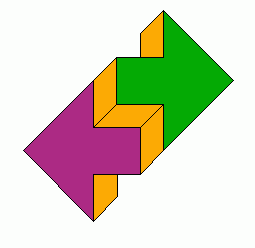
| Mach's illusion. |
|---|
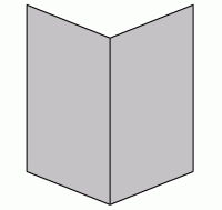
As with most illusions, this uses several forms of deception. The following picture shows in the ovals, the central illusion, which is nothing more than Mach's "open book" illusion, shown to the right. It can be seen as facing pages of an open book, or as the front and back cover of a an open book seen from its back. (Or, simply as two mirror-symmetric parallelograms.) This simple isometric illusion is the basis of the ambiguous staircase illusion as well as many others.
In Fig. 4 above the Mach open book illusion is used in the gear teeth, only this time the open book has a spine. Let your eyes follow the gear teeth left to right and somewhere along the line the tooth tops become tooth valleys or vice versa, and you just aren't sure where that happened. This is a distinctly different use of the Mach illusion from that used in the pictures where the gear teeth mesh.
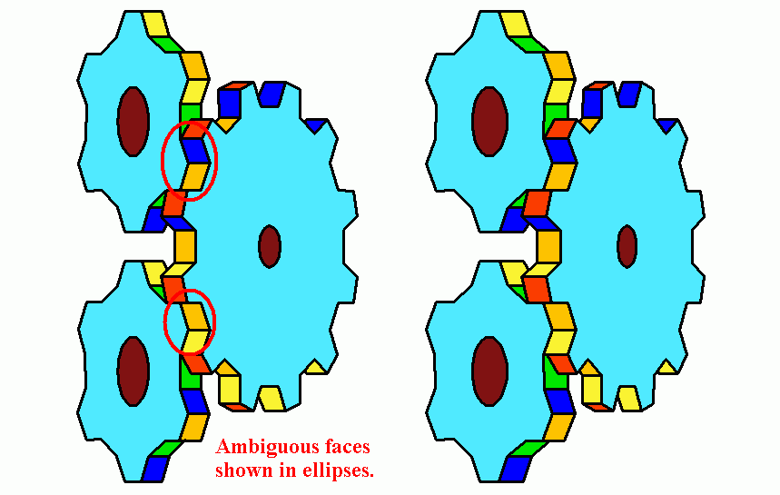
The 2D versions of these came first. This raised the question "Could they even be rendered in 3D". The drawings are isometric, which have no classical perspective (no vanishing points, which give apparent depth to flat pictures). But you can still employ stereo parallax in isomemtric drawings, for the stereo disparity overrides weaker depth clues. That's easily accomplished with ellipses, wheels and gears by altering their width to height ratio. The two gears of the left eye picture are widened horizontally, and the larger gear of the left eye picture is made narower. This is done only on either side of a vertical line passing through the illusory meshed gear teeth. In the CAD drawing, this breaks some of the points where lines join, and these must be repaired by hand. All this surgery was done only on the left eye picture. Then when all was fixed in the CAD drawing, the drawing was converted to a GIF, and colorized with a paint program. The colors help to emphasize the illusion, but must be done consistently. Notice that the left gears have teeth with orange tops, but the right gear has orange valleys between the teeth. This is necessary because in the ambigous regions where the teeth mesh, the orange top and valley are the same parallelogram. Similar constraints apply to yellow and blue faces. Coloring these can warp one's mind, leading to mistakes. If any mistakes remain, please let me know.
One might even say that the "colors transfer from one gear to the other" where the teeth mesh. Now if someone wants a real challenge, how about making an animated GIF of these gears rotating in 3d. (I can supply the original CAD structure in DXF format if anyone wants to try.)
Return to top of this page.
Return to illusions page
Return to front page and main menu.