The Chinese South-Pointing Chariot.
|

Many ingenious mechanisms are devised with no "practical" purpose in mind. They are examples of invention for the sheer fun of it. This phenomenon occurred early in many cultures. The classic mechanisms of the ancient Greeks were often just "toys", to amaze and entertain. Hero(n) of Alexandria (c. 10–70 AD) built a slot machine (insert a coin and it dispenses holy water), a clever hydraulic mechanism for mysteriously opening temple doors when a burnt offering heated water beneath the altar, and a cute little engine that whirled around under the force of steam through it (like a rotary lawn sprinkler).
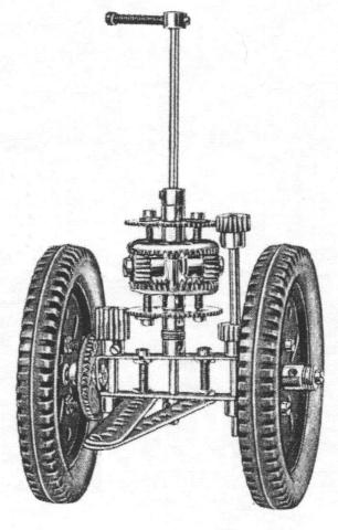
These were rather simple contrivances compared to the legendary "south-pointing chariot" from China. It was a two-wheeled chariot, pulled by a horse, with a statue of a person riding on it. The statue's arm was extended, pointing south no matter how the chariot moved. The chariot could travel in curves, loops, or any convoluted path, even backward, but that statue stubbornly continued pointing South—but only if the ground surface was flat and level and the wheels didn't slip.
Though legend has this invented in as early as 2600 BC by the Yellow Emperor Huang Di, the first historically confirmed version was created by Ma Jun (c. 200-265 AD). Its secret was a geared mechanism inside the enclosed body of the chariot. The differential motion of the wheels drove the gears, which in turn causes the statue to rotate the same angle as the carriage turns, but in the opposite direction. Simple to say, but not so simple to invent. In fact, history tells us this closely guarded secret was lost several times and reinvented, and in each case the inventors received much acclaim.
When this chariot was shown in public ceremonies, the mechanism was hidden in an enclosed chamber underneath the statue. Some people supposed that the chamber concealed a person with a magnetic compass, continually rotating the statue to keep it pointing south. Some even thought a magnet could be strong enough to turn the statue by itself.
|
But what use was it? Probably only ceremonial use, to impress, puzzle and entertain an audience. Some historians fell into the error of assuming it might have had military uses (as the legends claimed), such as guiding armies traveling in a desert at night, or in smoke or fog. That's hardly likely, as the carriage only works well on solid and level ground (as a parade-ground). Potholes and even small hills would compromise its accuracy quickly. Also, the wheels must not slip or slide. Legend even tells of a similar "south-pointing ship", but this goes beyond credibility, for the mechanism requires a flat, level and unmoving surface to work properly. That was more likely a magnetic compass, which was known in China during the Qin dynasty (221-206 B.C.). It certainly was a more practical and reliable tool for navigation. The south-pointing chariot was not.
The mechanism had four wooden gears, arranged in much the same way as the differential gear of an automobile. But it was being used backwards. Additional, conventional, gearing was required to connect the differential to the wheels. The wheels drove the gears, which in turn rotated the statue. It could have been used to drive the wheels, if only they had an engine of some sort to power it. Sometimes a clever idea isn't implemented fully because other technology isn't available yet to support it.
Hearing it described, even with detailed plans, may not convince you that it works as claimed. You have to build one, and experiment with it. Hobbyist mechanics build many variations, from small desk-top models to full size carriages pulled by ponies or horses. Steel construction toys used to include plans for one, back when such toys were intended to educate youngsters about mechanisms and physics. The internet has many sites with pictures of models, and often complete plans for building them, even parts lists. As my readers know, I don't do this here. They don't allot me that many pages. Also, I credit readers with enough cleverness (and independence) to see an idea and then figure out their own personal design to implement it. I do give pictures and some guidelines.
|
The differential gearing is the heart of this project and requires either 2 crown gears and 2 pinion gears, or 4 bevel gears. You'll need a shaft coupler with 3 set screws (grub screws), or some other way to fasten perpendicular shafts together. These can be rigidly fastened, for the gears of the differential unit turn freely on them. Fig. 3 shows the use of Meccano (or Exacto) parts (generally the best quality readily available), or Eitech (metric standard), parts. I keep a supply of size 6 washers (metal and nylon) to use as spacers for this sort of mechanism.
|
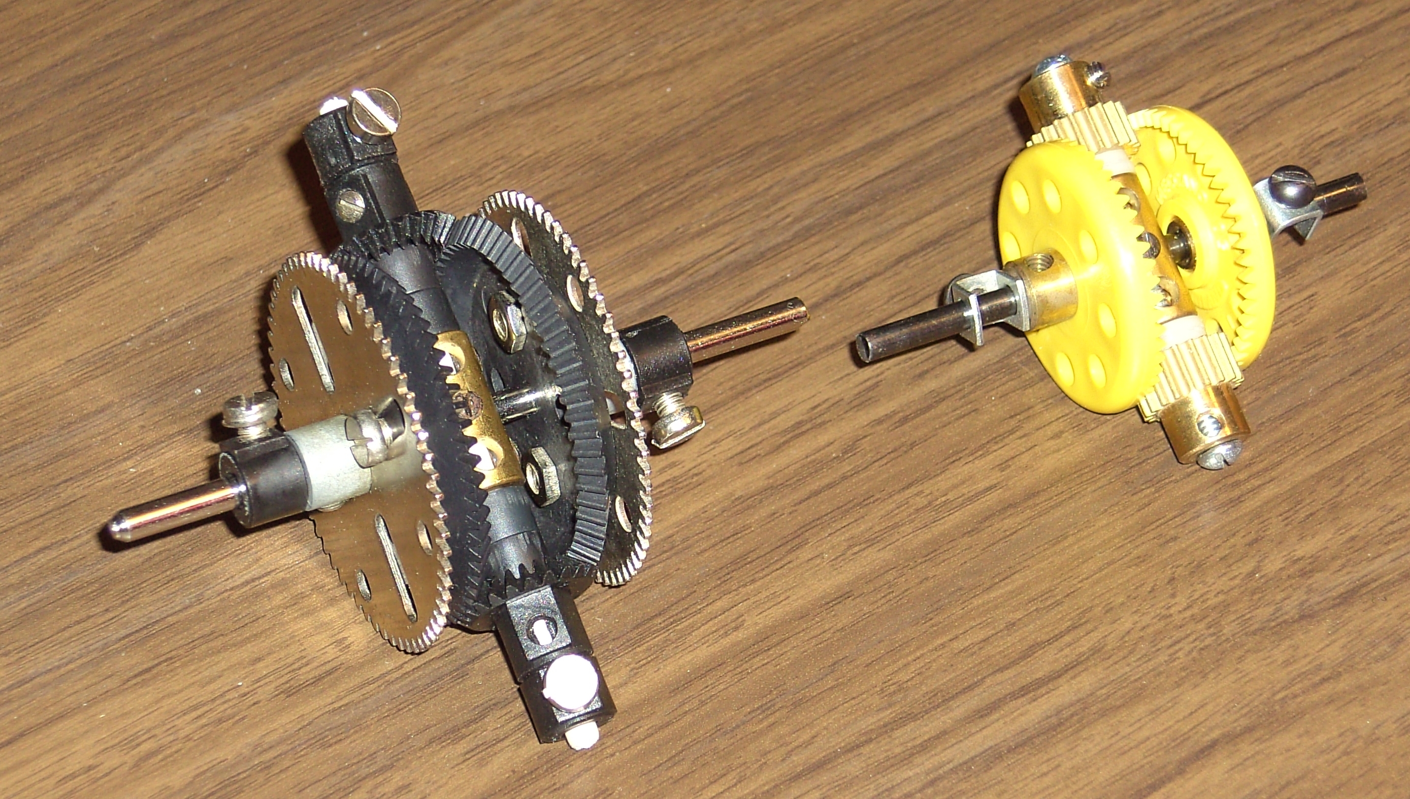
| Fig. 4. Differential with bevel gears, using Eitech parts (left), and one with crown and pinion gears, using Meccano parts (right). The gears' grub screws will be removed, since all these gears must rotate freely on their shafts. |
|---|
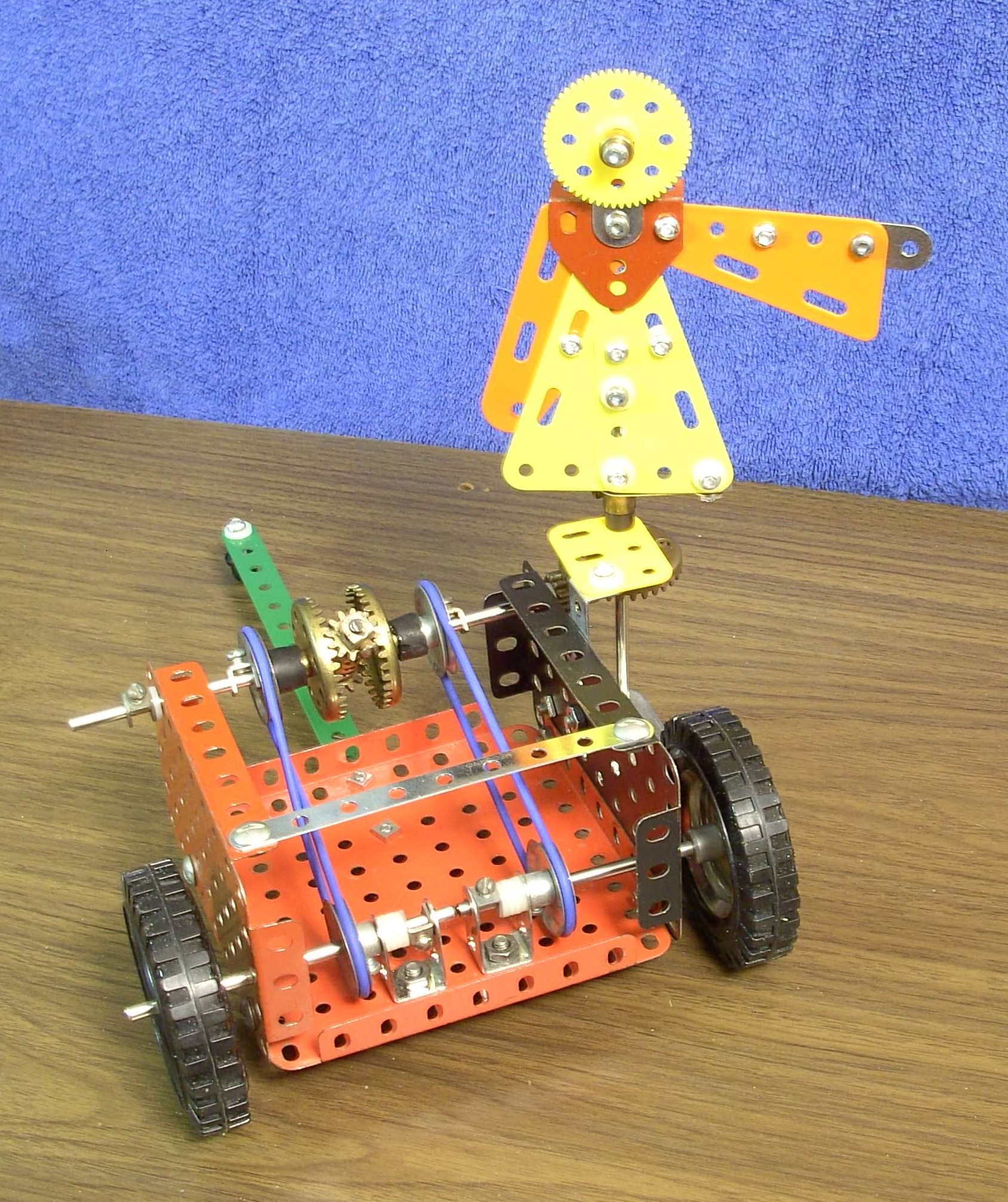
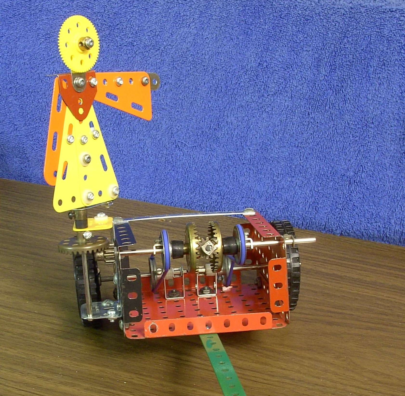
I've made several versions of this toy. But for this article I made a larger one with the mechanism exposed so it could be photographed with all important components fully visible. It's not elegant, but it works. Most hobbyists use Meccano parts for such models. But I chose to use Erector parts since I had a lot of them. The differential is the Lanchester design, but rotated 90°. I could have used spur and pinion gears to link it to the wheels. I took the simpler route and used rubber O-rings (blue) and four pulleys. One belt must be crossed to reverse the direction that it drives the differential. [With gears, an extra idler gear is required to accomplish the same reversal.] The pulleys link to the crown gears of the differential with short sections of rubber tubing, since these must turn independently of the axle that passes through them.
|
| Fig. 5. Open version of the south-pointing chariot. Mechanism and housing mostly of Erector parts. |
|---|
|
In the time-honored tradition of tinkerers I didn't do any calculations, I just let the design evolve as I built it. I tested it and then experimented with different wheel diameters and adjusted the spacing between the wheels until it worked properly. Once the gear box is built, these are the only two remaining adjustable parameters. I wouldn't be at all surprised if this was the way the original inventor did it.
However, the math isn't that bad. The separation of the wheels is 14 cm, and the wheel diameters are 7 cm, for a rotation angle ratio of 1/2. The pulleys are all the same diameter, so the belts have rotation ratio 1. If you hold one wheel stationary and rotate the other, you notice that the small gear in the differential rotates on the stationary crown gear while the other crown gear drives the small gear, for an additional rotation ratio of 2. The gears of the differential have a gear ratio R, but the gears under the statue are in the reverse order, with a gear ratio 1/R, for a combined ratio of 1. Multiplying all these ratios gives 1, and the twist in one belt reverses the statue's rotation to be opposite to the rotation of the chariot. An additional small fudge factor is required to compensate for the tire width.
|
It is best to use rubber tires on the wheels, so the wheels do not slip. Rubber O-rings of the right size work well. Also, weight is an asset. Heavy wheels are less likely to slip on smooth surfaces. Or you can add "load" in the bottom of the box.
Oh, by the way... Why does the Chinaman point south instead of north or some other direction? Actually he simply continues pointing in the direction he was initially set to point. In Chinese culture, south, being the direction where the sun reached its highest elevation, is more important than north, and is considered the reference direction on maps.
Other designs.
|
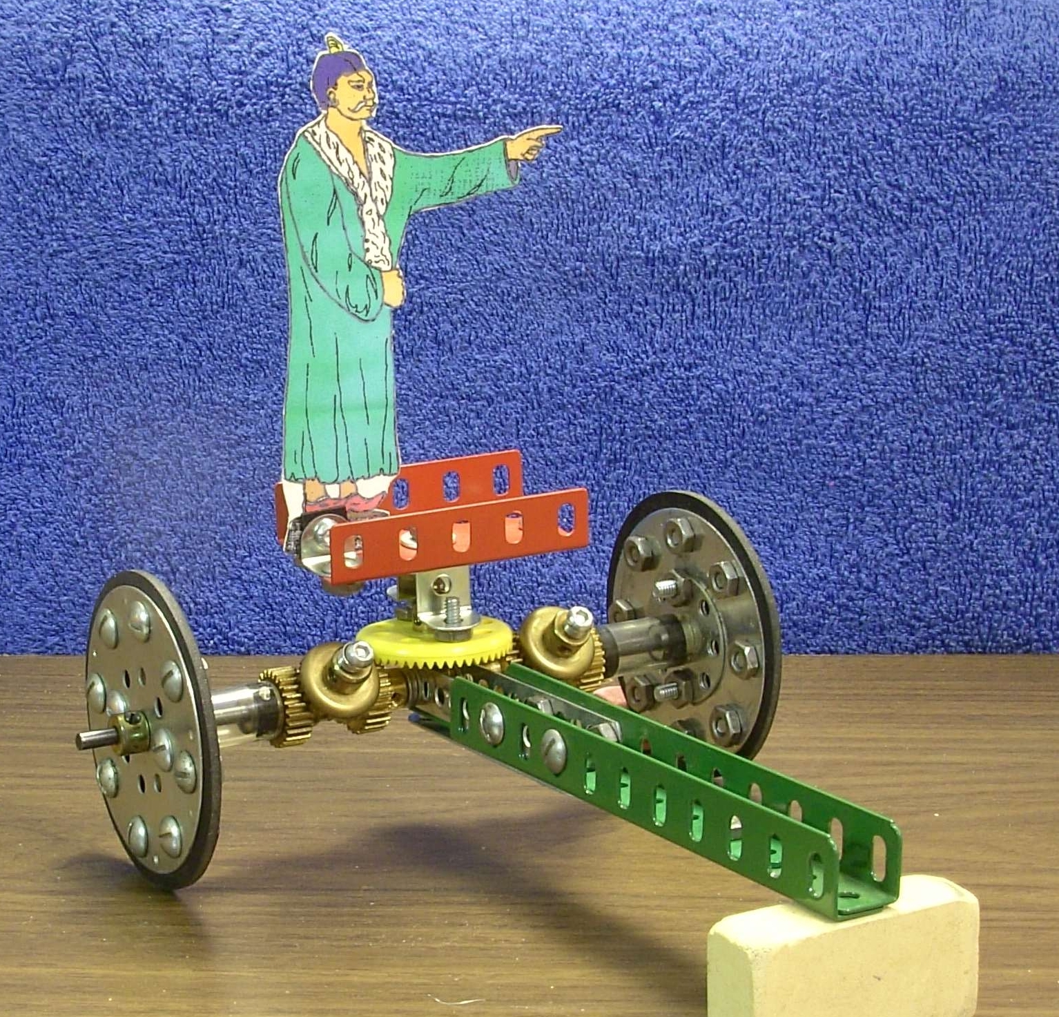
The first model I built was the Lanchester design, of Erector parts, Fig 8. All of the wheels and gears associated with the differential must turn freely on their axles. Short pieces of plastic tubing connect the outer gears to the outer crown gears of the differential. The necessary reversal of direction of the drive from one wheel was accomplished with an idler gear, mounted on the two fiber plates at the left. The carriage wheels have independent axles.
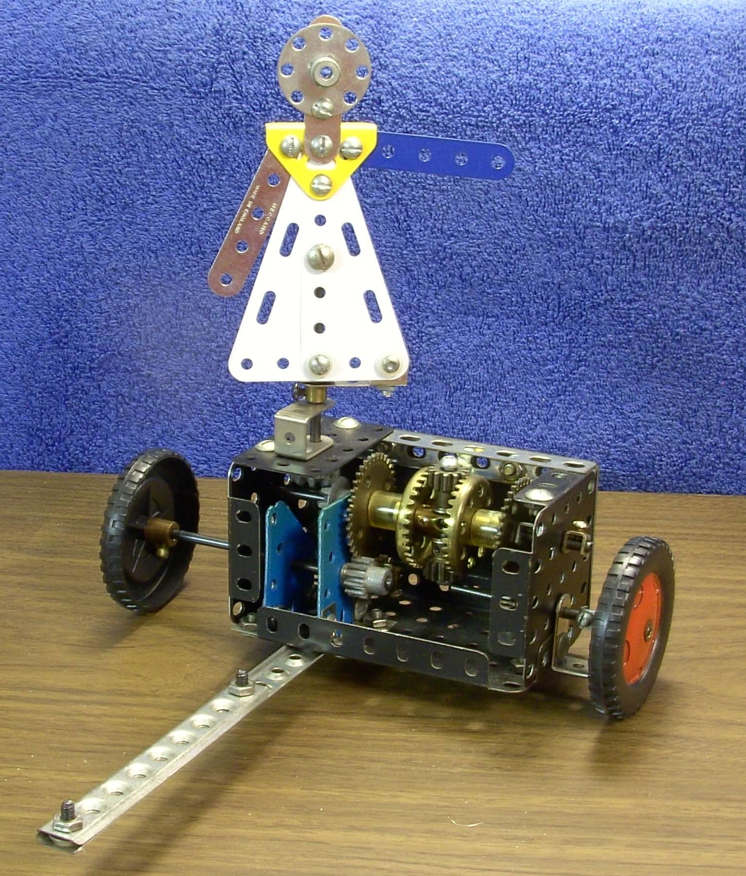
My second model used parts from Meccano sets, Fig 9. I followed an elegant construction (called the Nuttal design) found on the web. It required gears of specific sizes, so I ended up ordering quite a few brass gears. Fortunately there are still sources where you can buy individual parts, even rare ones. This model has everything visible, and though the principle is the same, the gearing is quite different from most museum models. The model is completely symmetric about the statue, and no reversal gimmick is necessary. The Nuttal design has just one long axle for both wheels. The wheels must move independently, so they are not fixed to the axle. Note the heavy rubber-rimmed wheels, for better traction.
|
Some web links.
South Pointing Chariots. Many different models with plans and instructions for some of them.South Pointing Chariot from the Wikepedia. History, legends and a brief explanation.
Girders and Gears, a fabulous place to buy parts for hobbyist projects.
Exacto parts (Erector and Meccano compatible, 1/2 inch hole spacing). Every English standard consruction set part ever made, and more.
You can see stereo 3-D pictures of my models here. I'd be happy to see any of your creative versions. Email me at dsimanek@lhup.edu.
For Sam Murphy
Pictures large size, and captions and credits. Fig. 1. Chinese South Pointing Chariot. Model by George H. Lanchester. Science Museum of London.Fig. 2. Mecccano Model, Lanchester design. Meccano Magazine, Jan 1957.
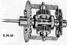
Fig. 3. Differential. Differential, from instruction book of Meccano Standard Mechanisms, 1934, UK Edition.
Fig. 4. Differential gears. Differential with bevel gears, using Eitech parts (left), and one with crown and pinion gears, using Meccano parts (right). The gears' grub screws will be removed, since all these gears must rotate freely on their shafts.
Fig 5. Rear View. Open version of the south-pointing chariot. Mechanism and housing mostly of Erector parts.
Fig. 6. Front View. Front view.
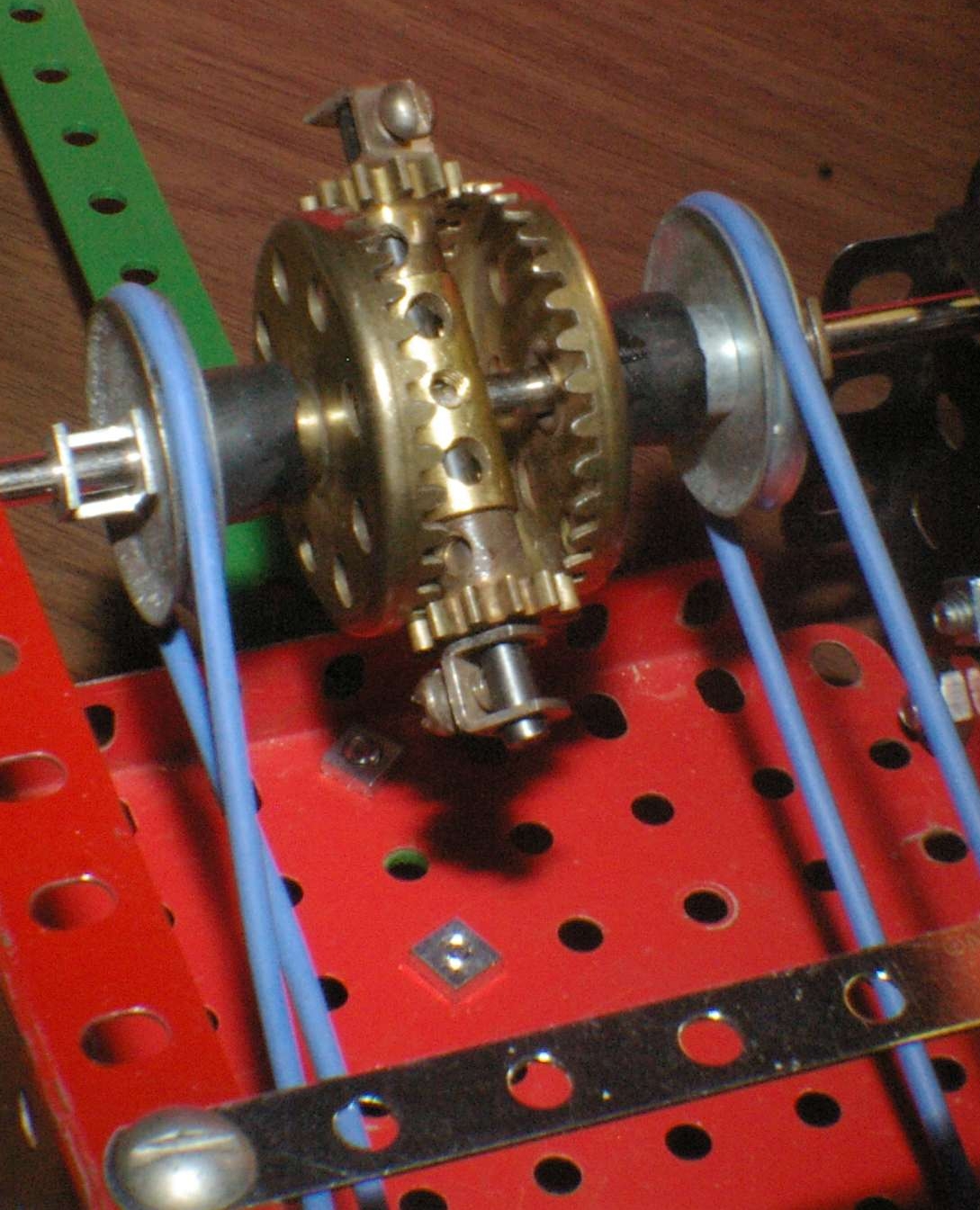
Fig. 7. The differential. The differential.
Fig. 8. Lanchester design. Erector model, modified Lanchester design.
Fig. 9. Nuttall design. Nuttal design, Meccano parts.