Crowned pulleys.
Real-world problems in physics sometimes take quite a while to figure out, unlike the contrived problems in textbooks that must be solved by next week.
 |
| Threshing machine (1940s). Photo by Donald Simanek. Note the drum pulley on the tractor. |
|---|
Such a problem first came to my notice when I was a child growing up on an Iowa farm in the 1940s. At that time few farmers could afford grain threshing equipment, and the custom was to share a threshing machine that would go from farm to farm. The farmers brought the shocks of grain from the field to the machine, and then took the threshed grain to storage. The machine blew the straw into a huge pile. Too young to be asked to do any of this heavy work, I watched the whole process with fascination.
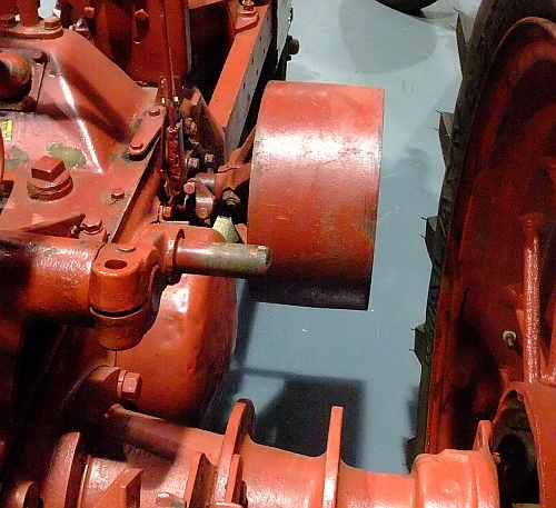 |
| Crowned drive wheel of an old tractor. Photo by Donald Simanek. So subtle it's not noticeable at first. |
|---|
The threshing machine seemed huge, and was driven by a flat leather belt powered by a stationary farm tractor. The belt was perhaps a foot wide or more. Of course the thresher and tractor had to be properly aligned, and blocked so they wouldn't move. What puzzled me was how that 20 foot long belt could run all day and remain on the cylindrical pulleys without wandering off. The belt might not track properly until the tractor was properly positioned, but once that was accomplished, it usually needed no further attention. No one I asked knew the answer. "It just works," they said.
At the university, we physics majors studied mechanics and even some material on machines. But this particular problem was never addressed by textbooks or in class. By then it had settled to the cobwebby recesses of my mind. After a career of teaching physics at the university level, I never saw this problem in any textbook. After retirement, I kept busy with a web site, mostly about physics, and people would send me questions by email. One of these asked about flat belt tracking.
Foolishly thinking I could brainstorm this myself, I first considered friction effects. Then I got smarter and sought out a real farm tractor. It had the usual drum cylinder for flat leather belts, and then I noticed that this cylinder wasn't of uniform diameter, but was slightly larger diameter at its center. Other belt-driven machinery revealed the same thing. Aha! Could this somehow be causing the belt to ride onto this elevated center section and stay there? But why would the belt prefer a larger diameter, and greater tension? It seemed counter-intuitive. But one thing I've learned in my years in physics is that one's naive intuition is usually wrong.
Back to the laboratory, and more experiments. At first I suspected friction had something to do with it. But the friction acts in the wrong direction, opposite the observed centering movement of the belt. Of course friction is important to the operation of the machine, for without it the belt wouldn't turn. But perhaps something else is going on. Along the way I remembered the old adage, "Sometimes an hour in the library can save you weeks in the laboratory." I searched engineering mechanics books, a genre of literature I had seldom ever consulted before. And I came up blank. These books didn't mention such mundane matters as pulley centering. The internet wasn't much help either, except to describe this kind of pulley as a "crowned pulley", and to give specifications for the elevation of the center as a function of the pulley radius. It's always easier to find information about something when you know its name.
At a used-book sale I gravitated toward the engineering section, and there I found an older textbook Elements of Mechanism, Third Ed. by Schwamb, Merrill and James (Wiley, 1921), and was astounded to see an excellent discussion that tackled this question head-on, and gave a very good explanation that even a physicist could appreciate and understand. I love older textbooks, for they had real information and good explanations. This is the sort of book that libraries too frequently discard because (1) it doesn't get checked out, (2) it is a textbook, and (3) it is old (1921). Newer textbooks, in spite of their obscene size, have so many glitzy color pictures that there's isn't enough space for the necessary words. Here's what this textbook said:
|
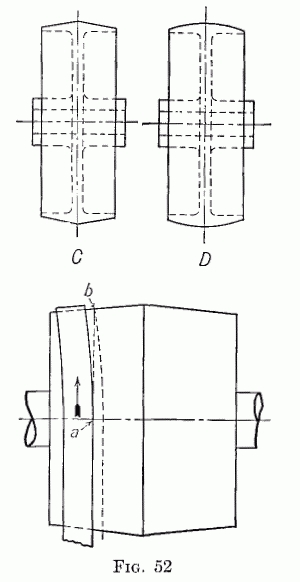
If a belt is led upon a revolving conical pulley, it will tend to lie flat upon the conical surface, and, on account of its lateral stiffness, will assume the position shown in Fig. 52. If the belt travels in the direction of the arrow, the point a will be carried to b, a point nearer the base of the cone than that preposition shown by the dotted lines. Now if a pulley is made up of two equal cones placed base to base, the belt will tend to climb both, and would thus run with its center line on the ridge formed by the union of the two cones... [The amount of crowning varies from about 1/16 inch on a pulley 6 inches wide to about 1/4 inch on a pulley 30 inches wide.]
The belt in contact with the truncated cone lies on the pulley relatively flat and undistorted in shape. But along the dot-dash (horizontal) line at a the belt moving upward makes first contact with the pulley. As the belt moves from a to b without slipping, it moves along the dotted line ab to a point farther up the incline of the cone, and this process continues until the belt rides onto the apex. It's just geometry!
|
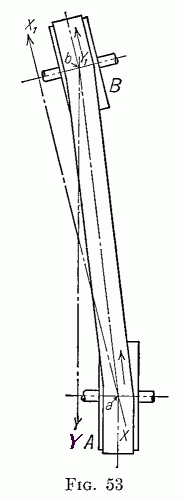
Now let's look at the case of a flat belt running over two cylindrical pulleys whose axles are misaligned. Will the belt crawl to the right (where the belt tension will be higher) or to the left (where the tension is lower)? After thinking it through, try it (see below) and you may realize that a different reason must be sought than the one we found above, since your intuition may have misled you again. Quoting the textbook referenced above:
When pulleys are located on shafts which are slightly out of parallel, the belt will generally work toward the edges of the pulleys which are nearer together. The reason for this may be seen from Fig. 53. The pitch line of the belt leaves pulley A at point a. In order to contain this point the center plane of pulley B would have to coincide with XX1. Similarly, the belt is delivered from b on the under side of pulley B, into the plane Y1Y. The result of this action is that the belt works toward the left and tends to leave the pulleys.
In Fig. 1, each new piece of belt coming onto the pulley was carried, without slipping, to a point higher (to the right in Fig. 1) on the slope. In Fig. 2, each new piece of belt coming onto the pulley is "laid onto" pulley B at a point slightly lower (to the left) on the tilted pulley, and is carried around it without slipping. Also the belt on the backside, coming down from pulley B to pulley A wraps onto pulley A at a point slightly to the left, an action mirroring what's happening at pulley B.
An example of a crowned pulley can be found in the drive wheel of a shop band-saw. This demonstrates that the principle also works with steel belts, which are much more rigid laterally than leather or rubberized canvas belts.
What I like about this puzzle is that (1) the behavior on the crowned pulley is counter-intuitive; (2) most of the initial hypotheses you make will turn out to be wrong; and (3) some explanations of the crowned pulley seem so "right"—until you apply the same reasoning to the parallel shaft problem, then it's "back to the drawing-board". I like puzzles that have several levels of apparent paradox and counter-intuitive features. They teach us to use, but not to trust, our intuition, which is a good thing. Intuition can sometimes be a part of the problem solving process, but at some point, it must give way to "sweating the details" and being ruthlessly critical of "plausible-sounding" answers.
Test it yourself.
Even after reading the explanation, you may still be skeptical of it. You may even be skeptical that it really works this way. Good! So I urge basement tinkerers to try it with real belts and pulleys. I used Erector construction set parts, some wood turnings, metal cylinders and rubber bands, only because they were handy.
|
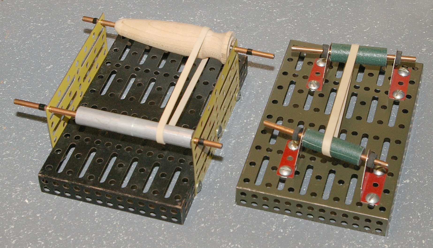
Fig. 3 shows my two models. The model on the left has a wooden file handle as a pulley. This serves to illustrate how the rubber band will migrate along the wooden pulley from the narrowest part at the left, to its largest diameter. The file handle has both convex and concave profiles. Placed in the concave part, the rubber band will quickly rise up the slope and will stabilize at a larger radius, even if that is the very narrow portion near the right end. In the misaligned pulley model, it's better to use wooden dowels, or cover the metal cylinder surfaces with something like cloth tape to prevent slipping. The second model has two misaligned pulleys. When turning, the belt migrates to the end where the pulleys are closest together.
Responses to readers.
This article generated more responses than I expected. Some readers were happy to have an answer to something that had puzzled them in the past. Here's a typical email:
Donald,

  I enjoyed your article, it finally explains what
I have wondered about for years. I went through
the same futile search as you trying to find an
explanation for what seemed counter-intuitive.

  The same idea has been used for years on magnetic
tape machines. I learned years ago as a tech in the
consumer electronic business that the pinch rollers
had to be crowned or the tape would wander and get
chewed up, or cause loss of contact with the heads.

 We sometimes had to sand a crown back on the
pulleys or rubber idlers to get them to track
correctly.

    Thanks for the enlightenment.

    Best regards, Steve
But some readers were not satisfied. They wanted more. One engineer was familiar with wide conveyor belts and exercise treadmills which must also "track" properly. A little investigation shows that their drive rollers, while cylindrical over most of their length, are often tapered to slightly smaller diameter only near their ends. This is enough to ensure tracking. In that case, the explation given above is still essentially applicable. Apparently some such systems use a dynamic electronically controlled feedback system to tilt one of the roller axes slightly in response to any belt wandering. In industrial settings a conveyor belt must maintain tracking even when its load isn't balanced, as when heavy boxes or crates are being transported.
Correspondents also got me to thinking about whether band saws really work on the same principle. Certainly their large drive wheels are crowned. Band saws generally have a knob to adjust the drive wheel axis tilt in order to center the blade on the wheel. Also the crowning seems to be of a radius nearly equal to that of the drive wheel itself. So it is as if the blade is riding on the diameter of an equatorial slice of a rotating sphere. While a belt of rubber, canvas or leather can have torsional flexing, the rigid steel belt resists that kind of deformation strongly. More information would be welcome.
Metal saws, being more rigid than drive belts, might be a special case. I found a reference that suggested that very large band saws in sawmills sometimes have their blades slightly crowned.
|
Some readers thought that an explanation using forces would be "better". They offered arguments that had one fatal flaw, in my judgment. They imagined the portion of the belt at the top of the drive pulley to be a "body" and tried to do a force analysis using F = ma on that body. The argument is seductive, supposing the belt moves "up" the slope of the pulley in response to a force the pulley exerts on the belt. Their arguments bogged down because that small part of the belt they were considering isn't a simple "body" in the usual sense, but only an ever-changing portion of the larger body of the belt.
Now you could probably make a force analysis of this system, but it certainly isn't elementary physics. My question is "Is it necessary to do that to understand what's happening?" Also, if you are hoping to find a force due to the pulley that acts on that portion of the belt to move it in the direction of larger pulley diameter, you are out of luck. The force normal to the belt-pulley interface (N) has no component along the pulley surface, either up or down the slope. And don't hope that friction is the force that moves the belt, for friction always acts to oppose the relative motion of the two surfaces. But in normal operation the belt does not slide up or down the pulley surface. There is a force due to friction (f) acting on the belt and directed up the slope, but it is opposed by equal and oppositely directed net force due to the long "straight" portions of the belt, for a net force of zero. It prevents the belt sliding down the slope (which is a good thing) but does not produce sliding up the slope. Once a portion of the belt lies in intimate contact with the pulley surface, there's no subsequent net motion of that portion of the belt relative to the pulley surface. The belt does not slide up the slope.
My article did not address the "elephant in the room" question: "Once belt tracking stability is achieved, why does it persist? What happens when the belt wanders slightly offside in either direction that causes it to move back where it belongs?" Here, I think, you'd have to deal with the belt torsion issue, and that could get messy. That's why I limited my article to the simpler part of the puzzle.
Other readers hoped for an energetic analysis, to somehow show that the belt "seeks" a position of a relative minimum energy. None have worked this out convincingly. This is a system where there's a continuous input of mechanical energy. It isn't a closed system.
Tim Walker sent some useful web references:
Prof. Simanek,
I am a consulting engineer working with manufacturing processes involving paper, film, and foil materials. Though these materials are not exactly belts and pulleys, the physics of belt/pulley applied to web/roller (a web is the industry term for a long flexible material, such as paper, film, or foil, but also nonwovens and textiles).
The tracking on diameter variations is a double-edged sword of web handling. In narrow belt handling, a crown’s centering action is great. However, in wide web handling, having both left and right sides of your web tracking to the center is a bad thing (a gathering event or wrinkle forms, which is a defect or cause of breaks in our processes).
The diameter tracking effect is a combination of two things. 1) The rule of parallel or normal entry. 2) The upstream curvature induced by the lateral tension variations created by the speed and elongation changes of the web on the crowned roller.
Here are some internet resources that can help explain all this.
An article I wrote about the #1 rule of web tracking.
Here are some slides from Jerry Brown, another consultant in my area, on the #1 tracking rule. The Normal Entry Rule.
Lastly, a great website discussing the use of crowned pulleys in band saws, including a wonderful YouTube video. Crowned Pulleys.
Enjoy.
Timothy J. Walker
The band saw is indeed a special case, for it is a very stiff belt compared to the leather, rubber or fabric belts that I discussed.
Another unaddressed consideration here is the length of the belt relative to the drive pulley radius. Also, I have observed that folks who make 1/12 scale working models of industrial machinery generally use much more obvious (smaller radius) crowning of pulleys.
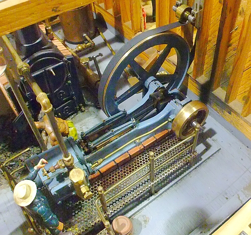 |
| 1/12 size steam engine model. Photo by Donald Simanek. Note the obvious crowning of the small brass pulley. |
|---|
Research continues.
Research continues, discovering new twists on flat belts.
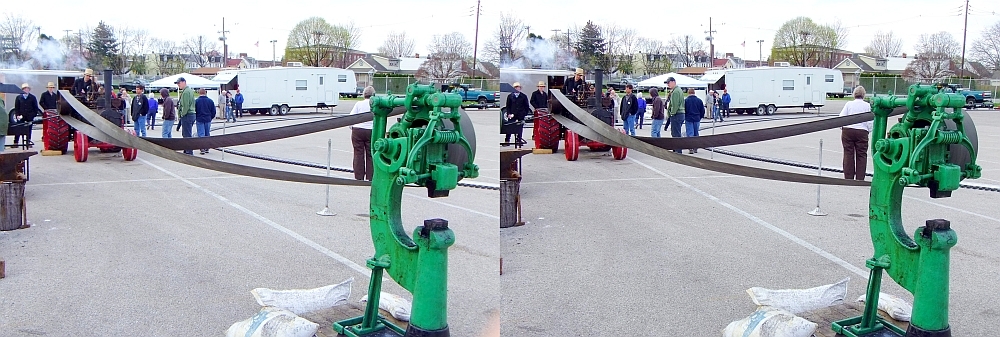 |
| Flat belt with a twist. York Model Engineering show, April 2013 The pulley on the right is wooden, narrower than the belt. Cross-view stereo by Donald Simanek. |
|---|
Twisted belts can be necessary in some cases just to reverse the direction of the driven machine if there's no other way to do that.
The twisted belt is often a way of coping with aerodynamic wind effects on long belts used outdoors, and with standing waves that can develop on long belts. Some even advocate a half-twist, so the belt is a Mobius strip, thereby equalizing belt wear on both sides of the belt. Technically, the Mobius belt has only one side. This requires disconnecting the belt's splice and reversing one end of the belt before re-splicing. That's not practical on continuous belting.
It is also said that a twist in a long belt improves pulley tracking and reduces the chance of the belt wandering off a pulley. It also, obviously, increases the contact area of the belt with both pulleys, reducing slippage. However, I don't see this as a problem requiring a solution, since if the tension is correct, flat belts seldom slip except when starting, or if the load suddenly changes.
Another trick is to invert one end of the belt inside out so there's a double twist in the belt. No re-splicing is necessary. This is only practical for long belts, however. It also has the advantage of equalizing wear on the two sides of the belt.
On the other hand, one fellow on a web forum discussion of these matters offers this:
You guys have it all wrong. It is twisted so the defrapitizer that connects to the ringselezer is funculated so that when the armanetar goes too fast it will governate the torsinal springethinger. If the belt runs in the backforward mode it will break windage so the atmospherical potiontiality is reversed so the throwrod is stopped before the pistonal is in its last throw. I hope this helps on the twisted belt theory.
I think that the narrow pulley (narrower than the belt) might act something like a crowned pulley, but that is just off the top of my pointy head. I do suspect that it would be impractical for long term use, as it might cause unnecessary stress and wear of the belt.
I'm not about to do the dynamic analysis of twisted belts, but those who use them say that a twist also improves lateral stability on the pulleys. Isn't it curious that physicists can invent ingenious new ways to skin Schroedinger's cat, but are silent on the problems of flat belt pulleys.