
by Donald E. Simanek
 Illusions and paradoxes never cease to fascinate. When we perceive something that seems to behave in an unexpected or impossible way, we realize that it is something new to our experience and we want to figure out what's going on. Visual illusions are the obvious example, but there are also tricks of physics and mechanics that seem paradoxical when first experienced. They challenge us to "puzzle out" what makes them work. These are often the basis of magic tricks, toys and illusions, or at least, instructive physics demonstrations. This column will explore some of these that may not be familiar to readers, with emphasis on those that you can DO or MAKE yourself. I will include explanations, as well as web links to more detailed treatments. Readers are invited to contribute their own favorites to me at DSIMANEK@LHUP.EDU.
Friction. There's the rub.
Let us all give thanks for friction. Without it our feet would slide uncontrollably when we try to walk, automobiles would spin their wheels and go nowhere, mountains would subside, weather patterns would be vastly altered. Nearly everything in our world would function differently without friction.Friction has the unfortunate side effect of dissipating kinetic energy, converting it into heat, which contributes to the inefficiency of machinery. Yet, without friction, it's hard to imagine how we could even manufacture that machinery. Some friction is a good and useful thing. A lot of it is too much.
How many of us can claim we understand friction? The details of intermolecular forces and surface films are complex and won't be dealt with here. But in everyday life there are just a few basics you need to know.
A little friction physics.
When bodies are touching, they experience contact forces at their interface. Thse obey Newton's third law: If body A exerts a force on body B, then B exerts an equal size but oppositely directed force on A. The contact force acting on a body has two components, one perpendicular to the interface (called the "normal" force, symbol "N") and one tangential to the interface (called the "force due to friction", symbol "f"). If there's no sliding at the surfaces, the force due to friction can be anywhere from zero in size to a maximum value f = ms N, where ms is called the static friction coefficient. If there is sliding, the force due to friction is given by f = mk N where mk is the kinetic friction coefficient. Friction coefficients are nearly constant for a given interface. For most materials, mk is slightly smaller than ms. Both are usually less than 1, but for quite "sticky" surfaces, can exceed 1.If there's no sliding of the bodies at their surfaces, the force due to friction is just large enough to balance the other forces on each body, preventing sliding. If there is sliding, the force due to friction is in a direction opposite to the direction of sliding (opposing the sliding motion). In short, the forces due to friction adjust in size and direction, responding to other forces so as to prevent sliding. But they have limits. When the limit is exceeded, sliding occurs, and the force due to friction acts in a direction opposing the sliding.
The oscillating beam machine.
 This is an old physics homework problem. A heavy uniform bar or beam rests on top of two identical rollers that are continuously turning in opposite directions, as shown. There's
friction between the rollers and the bar, and the sliding friction coefficient is constant, independent of the relative speed of the surfaces. Find the motion of the bar. What happens if the rotation directions of both wheels are reversed?
This is an old physics homework problem. A heavy uniform bar or beam rests on top of two identical rollers that are continuously turning in opposite directions, as shown. There's
friction between the rollers and the bar, and the sliding friction coefficient is constant, independent of the relative speed of the surfaces. Find the motion of the bar. What happens if the rotation directions of both wheels are reversed?
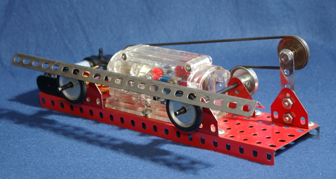 |
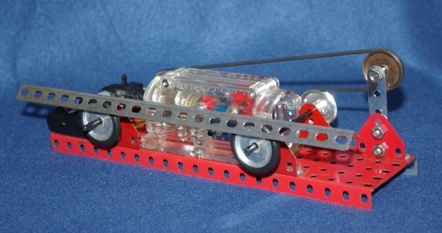
| Front view of oscillating beam machine. |
|---|
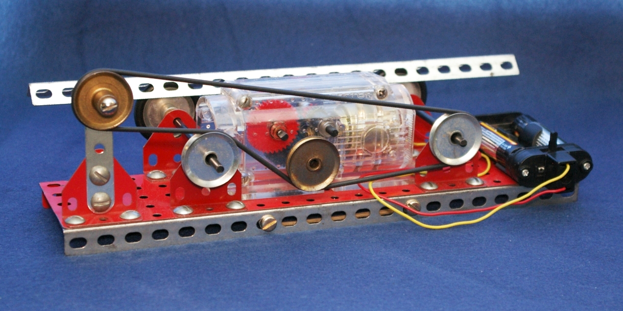 |
| Back view of oscillating beam machine. |
Many physics students had suffered through this problem, but few have bothered to make a working model of it. You can easily make it from construction set parts or whatever you have around the workshop. The rollers of my model are 1-inch pulleys about 6 inches apart with thick rubber o-ring tires. The rollers are driven by a pulley arrangement with a long rubber o-ring belt, and a standard Erector set motor geared down to slow speed. The beam is a 10 or 12-inch angle girder. Place the girder on the rollers so that it is an upside down V: ^. As the rollers turn, the girder oscillates back and forth in simple harmonic motion, without falling off the rollers. Sometimes the friction is a bit erratic, but the girder stubbornly refuses to fall off. I've had a model in a display case with a push button to activate the motor, and many people have tried to topple the girder without success. Of course, if the motor direction is reversed, both rollers rotate the opposite way, the girder smoothly moves in one direction and falls off.
I used a motor from a 1970s Erector set powered by two 1.5 volt AA cells. This motor has a gear-reduction train built in. Modern sets have a motor with higher speed and will require gears to reduce the roller speed to about 1 revolution/second. A rubber belt is best to transfer the motion to the rollers.
This is a fascinating toy to put on your desk and turn on whenever you wish to meditate on the futility of life. It could be a metaphor for some workplaces: lots of action, plenty of friction, but going nowhere and accomplishing nothing useful.
How does it work?
In the diagram the normal forces are labeled N1 and N2 and the corresponding forces due to friction are f1 and f2. The sum of the two normal forces is always equal to the weight of the beam, W. The actual sizes of the normal forces depends on the position of the center of mass, and vary in size so that the sum of the torques on the beam is always zero.If the center of mass of the beam were exactly between the rollers the load on each roller would be the same. If the friction coefficients were the same at each roller, the force due to friction would be the same at each roller. Then the beam would not move, and the rollers would slip under the beam. But such perfection is never attained. The initial position of the beam is not exactly centered, and the friction at the rollers not uniform. Suppose the beam begins to move toward the right roller. The right roller now takes a greater fraction of the load (the weight of the beam), the friction at the right roller increases in proportion, and the force due to friction opposes the beam's move to the right. If the beam then moves to the left and overshoots the central position, the left roller takes more of the load, and the left roller's friction forces the beam back toward the right. Whichever direction the beam moves, due to any unbalance, the rollers act to force it back toward the center. But the motion toward the center invariably causes it to "overshoot" the central position, and the back and forth motion continues. It has something in common with a pendulum, as a more mathematical analysis would show.
You could try to center the beam precisely and start it so as to achieve no oscillation of the beam. Good luck! Let me know when you succeed. There's a physics mystery here, that you don't discover until you build and play with this machine. Why does the slightest off-center initial position build up to a situation where there's a larger amplitude of beam oscillation than the initial displacement? What determines that amplitude? And why doesn't the beam ever come to rest? We leave these questions as exercises for the reader.
For those interested in the mathematical details, see:
http://www.lhup.edu/~dsimanek/scenario/demos.htm#plank.
[Article ends here.]
Figures:
toytrick1b.gif (header title)
arrows-c.gif (arrow illusion)
plank1.gif (plank on rollers, line drawing)
seesaw-back.jpb back view of model.
plank2.gif (line drawing, with forces shown)
Alternate pictures, not as good in my judgment.
seesaw3s.jpg (model, 3/4 view)
seesaw1b.gif (model, front view)
seesaw2b.gif (model, back view)
Mathematical details.
The forces on the beam are shown. The centers of the wheels are each a distance L from the centerline (dotted) of the apparatus. The friction forces are in opposite directions:f1 = µN1 and f2 = µN2
Take torques about the center of mass of the beam, shown by the "+" symbol in the diagram.
-Wx - N1L + N2L = 0 .
Then: Wx/L = N1 - N2 .
The net force on the beam is F = f1 - f2 = µ(N1 - N2) .
So, -Wx/L = (f1 - f2)/µ .
F = f1 - f2 = -µxW/L = -(µW/L)x = ma .
The acceleration of the beam is proportional to the negative of its displacement, and this is the definition of simple harmonic motion. Of course, the friction coefficients aren't perfectly constant, which superposes some variability to the motion, making it more interesting.
So what happens if both wheels turn the other direction? The friction forces change sign, and we get the result +(µW/L)x = ma, which tells us the acceleration of the beam increases with displacement, so the slightest initial displacement from perfect centering leads to still greater displacement, and the beam moves in one direction until it falls off the wheels.