 |
Capillary Wheels
We ignore the obvious problem of the time it would take the capillary to respond to motion of the wheel. (Let the wheel move very slowly.) There's a much more important mistake in the claim made for this machine. The forces due to adhesion between belts and water which supposedly make this work act not only in the narrow capillary between the belts but also anywhere that the water surface contacts the belts.
 |
The diagram shows what's happening. The key principle of capillary action is that adhesion forces along a meniscus line exert a net adhesion force proportional to the length of that line. Therefore, each length of meniscus can lift only an amount of water whose weight equals that adhesion force. In the diagram, the water outside the closely spaced plates is lifted until a volume of liquid V is above the reservoir water level. But inside the meniscus, each surface lifts that same volume of water, but in the confined space, lifts it higher. That's the conceptual explanation of capillary tubes which many textbooks fail to reveal. If the plates are brought closer together, the meniscus column will rise higher, but will still contain the same volume of water, independent of height.
So in our belt engine, the net downward force on the inside surface of a belt (in the narrow space between the belts) is the same as the net downward force on the outside of the belt. The net downward force on the belt sections which form the capillary is equal to the net downward force on the remaining two belt sections. There's zero net force on the belts even when there is a liquid capillary column between them.
But what if...
|
| Forces on belts with different coatings on inside and outside. Not to scale. The capillary width is exaggerated. |
|---|
No, it would not. Geometry thwarts you again. For a cyclic process of this sort, the belt passing into the water must pass out again. When all four segments of both belts are considered, and both sides of each, the net force due to the water acting on each belt is still zero.
Try variations. Try Möbius belts if you wish. Whatever you try, geometry stands in your way every time. Try such things over and over, and eventually you may discover that the geometry of the universe, and the physical laws constrained by that geometry are all conspiring to do one thing: absolutely prevent the possibility of a perpetual motion machine. This may be the most profound statement one can make about the way our universe works.
Additional discussion
Adhesion forces come into balance as the liquid rises in the capillary, responding by changing their size to achieve an equilibrium condition much as other elastic material contact forces do.
 |
 |
Our conceptual diagram at the top of the page can be used as a starting point for a derivation of the equation for the height of rise in a circular bore capillary tube. The lifting force around the circular meniscus at the top is proportional to the length of that circle, which is proportional to the radius, R, of the tube. The weight of water lifted is proportional to the volume of the water column, which is proportional to R2. Therefore the height of this cylinder is proportional to R/R2 which is 1/R.
Textbooks seldom discuss capillarity these days. When they do, they have misleading diagrams such as the ones shown here. The relative size of the capillary column and the meniscus are greatly out of proportion. This is yet another example of the fact that textbooks are one of the greatest obstacles to physics education. I'll admit that for a long while I failed to see the relative volume relations concept of this puzzle because this sort of picture was stuck in my mind, biasing all of my thinking on the matter. At the very least, textbooks which present such diagrams should include a disclaimer such as "Not to relative scale," or "This diagram is schematic only."
 |
 |
In 1864 Johann Ernst Friederich Lüdeke and Daniel Wilckens applied for a British patent on a device with two partially immersed wheels whose axes made a small angle so that on one side of the axles the wheels were close enough together that liquid could rise there by capillary action. Now you know why it couldn't work.
The reader is invited to consider what would happen if the inside and outside surfaces of the belts were coated with a material with a very different adhesion with water. Then consider what would happen if the outside of the wheels were coated with a material of different adhesion from the inside. This exercise should convince you of the importance of geometry in determining what is possible and what is impossible. In this case, if the wheel or belt intersects the surface and moves in a closed cycle, then what goes into the water must later come out of the water.
DES, 1 May 2003.
Another capillary conundrum.
|
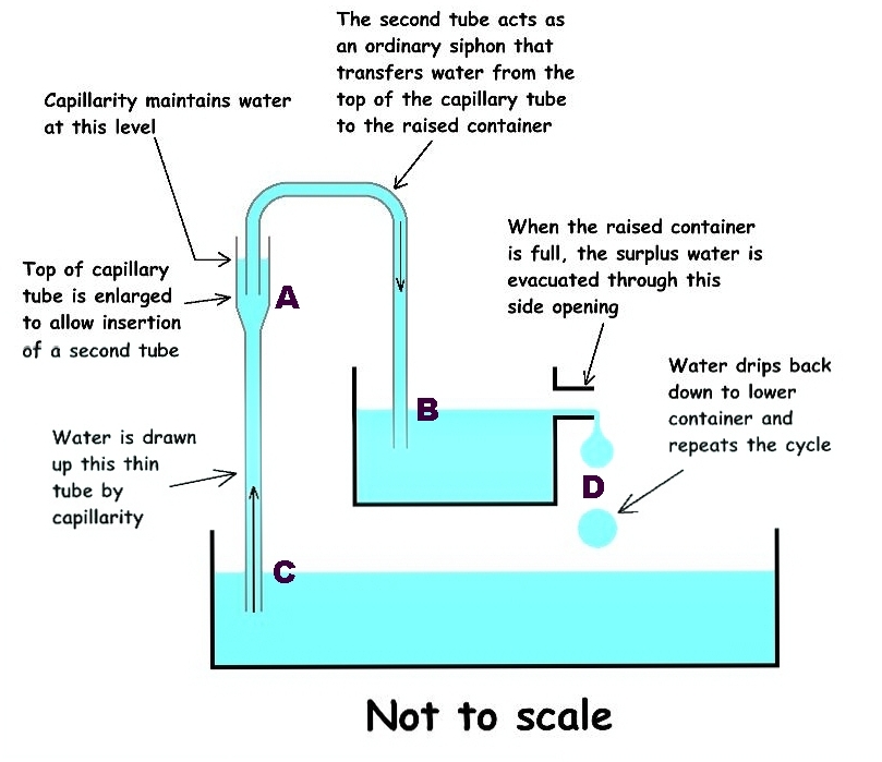
| The capillary siphon device. |
|---|
Seldom do I see a simple, yet original, perpetual motion device anymore. But this one is a refreshing surprise. This was submitted (April 1, 2012) by a fellow from Canada who knew it couldn't work, but wasn't sure exactly why. Do you?
This combines the capillary tube (discussed above) combined with an ordinary siphon. We have added letter labels to faciliate explanation. The thin capillary tube raises water from C to A. That lift occurs without the need for any input work from an external source. The upper end of the capillary tube is enlarged to a capillary ring surrounding a glass tube from A to B which serves to siphon water, in the usual way, from A to a lower outlet at B in a smaller reservoir. But B is still higher than the lower reservoir, C, so water flowing from B can easily drive a waterwheel at D to supply output work continually.
The smaller reservoir at B provides necessary regulation of the speed of output flow. Otherise the siphon might empty the tube at A, thereby destroying the capillary action necessary for the initial lift of water from C to A.
Notice how cleverly this circumvents the flaw in the classic capillary perpetual motion device. Instead of simply letting the liquid overflow the upper end of the capillary tube (which it refuses to do anyway), this device uses the tried and true siphon principle to intercept water from just below the upper meniscus of the capillary tube, without destroying the capillary meniscus. In fact, it increases the effective length of the upper meniscus, thus providing more lifting force there.
One skeptic points out that capillary tubes are short in length, and therefore there isn't much height for the secondary reservoir. This problem is easily solved by duplicating the arrangement at A to make a whole ladder of capillary tubes extending to a great height, thereby gaining more ouput energy as the water falls from that greater height back into the reservoir. Another naysayer points out that capillary tubes are very narrow, so there won't be much volume of water flow. But it is the principle that is important, and besides, we can just add any number of capillary tubes and siphons operating in parallel. That's what engineers are for.
It would be a shame if anyone found a pesky flaw in so elegant and simple a device as this. But if you do, please write, before we spend a lot of money building these on a very large scale.
Return to the main gallery.