 |
Gallery of ingenious, but perhaps impractical devices
Not all unworkable or impractical devices are invented to achieve perpetual motion. In this gallery we intend to collect a few which show the restless minds of inventors at work to produce better living for all. Some of these may have actually been used, and we welcome input from people who know of such cases.
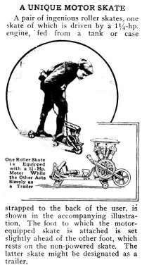
Power Boost for Roller Skates and Bicycles.
 |
 |
 |
| Scientific American. Dec 28, 1901, p. 43. | From Science and Mechanics, May 1912 (p. 618). | Source unknown, probably a science and mechanics magazine of the early 20th century. |
|---|
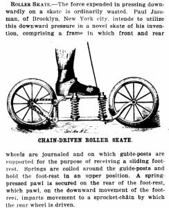
The inventor of these skates, Paul Jassman, solves two problems at once. His skates have springs, which you might think are to damp out up/down motion on rough surfaces. But in fact he wishes to utilize this up/down motion, proposing to couple it, using a ratchet and chain, to the back wheel of these roller skates.
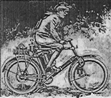
Another inventor of the same era adapted the same idea to a bicycle, using a pneumatic air chamber (like a shock absorber) on the seat to power the back wheel. This was supposed to be especially effective on bumpy surfaces.
We wonder if anyone ever built these, and if so, whether they learned the considerable skill required to control them on rough surfaces.
Modern innovations make life better.
 |
 |
|
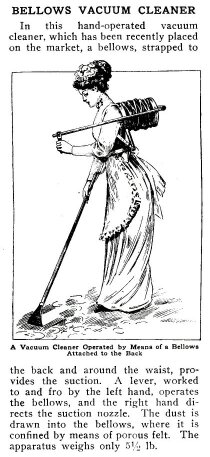
| Making housework easier. Science and Mechanics Oct 1911, p. 548. |
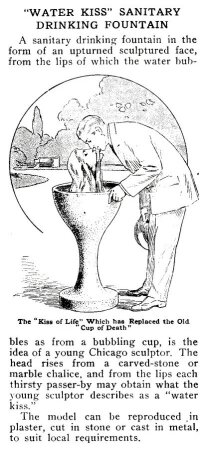
The Water Kiss Fountain. Science and Mechanics Jan 1912, p. 2. |
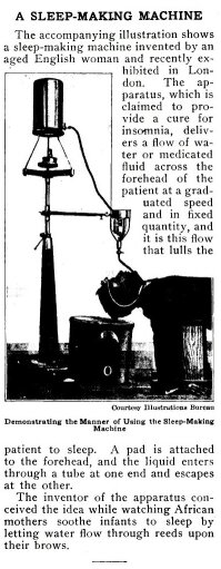
Aid to sleep. Science and Mechanics May, 1912, p. 672. |
|---|---|---|
The vacuum cleaner was good exercise for both arms. We wonder what the ladies thought of the water fountain. The sleep-making device may have worked, but you'd sure wake up with a stiff neck. Note the bucket to catch the water.
Easy as shooting ducks in a barrel.
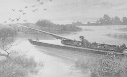 |
| Duck-Shooting Gunboat Science and Mechanics Oct, 1911. |
|---|
The caption gives this description without further comment:
It is a duck-shooting motorboat of shallow draft, provided with a long gun, which swings to any angle on its standard, and discharges an effective rain of shot.We wonder what the NRA would say of this, as a weapon for personal use. We also have some concern about "swings to any angle" and the advisability of firing it sidewise, considering recoil and its physical consequences.
Several persons have informed me that gunboats of this sort were actually built and used for hunting waterfowl commercially in both England and the USA. The shotgun was mounted in a flat-bottomed boat called a punt that was poled quietly, at night, close to a flock of birds on the water. This kind of hunting began in the USA in the 1880s, but by 1920 Federal laws banned market hunting and punt guns. Hunting for the fashion feather trade had threatened to make waterfowl extinct. I have not learned whether motorboats as large as the one pictured, or shotguns this long, were ever used.Popular magazines of science and mechanics of the period 1900 to 1930 frequently have items of this sort, often without specific documentation of the inventor's name or to a patent number. We still suspect that many of these were the inventions of the writers and artists, to "spice up" the magazine, but in this case the thing seems to be genuine.Here's a comment from Tim Walker in England: "These boats were in regular use in Norfolk, England, up until the 1960's. The gun was a sort of breech loading cannon, with a steel cartridge about 1.5" in diameter. You get a lot of shot in a cartridge like that. I have one in my collection. You lie in the boat and quietly paddle up on the ducks or geese. When close enough (25 yards or so) you fire. The best I know of was 23 ducks with one shot. I don't know of any of these weapons in use now."
The Aerial Railroad
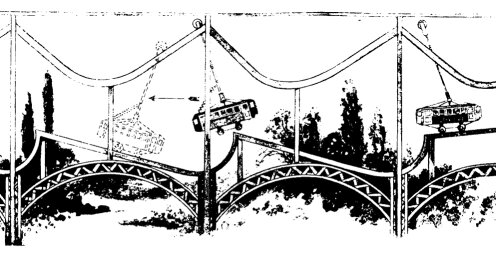 |
The March 1925 issue of Science and Invention featured this Aerial Railroad. By a combination of inclined ramps and overhead suspension from cleverly curved tracks the "trolley car" passenger vehicle could go forever without power. It falls while suspended in the air from the downward inclined track, swinging forward as it does. When it contacts the lower tracks its momentum carries it up the inclined track until the whole process repeats.
It's a good thing that this didn't, and couldn't possibly, work as described, for if it did, the passengers would have a ride more suitable for an amusement park than for comfortable transportation.
Self-Moving Railway Carriage
|
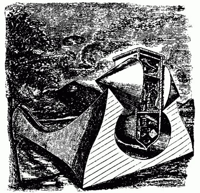
A correspondent to The Mechanic's Machine of London (Vol. 12, 1829) described this remarkable innovation in transportation. The claims made by its inventor were sensational:
...were it possible to make its parts hold together unimpaired by rotation or the ravages of time, and to give it a path encircling the earth, would assuredly continue to roll along in one undeviating course until time shall be no more.A series of inclined planes are to be erected in such a manner that a cone will ascend one (its sides forming an acute angle), and, being raised to the summit, descend on the next (having parallel sides), at the foot of which, it must rise on a third and fall on a fourth, and so continue to do alternately throughout.
...The most singular property of this contrivance is, that its speed increases the more it is laden; and when checked on any part of the road, it will, when the cause of stoppage is removed, proceed on its journey by the mere power of gravity. Its path may be a circular road formed of the inclined planes, but to avoid a circuitous route, a double road ought to be made.
I am indebted to a much-respected friend for the hint of this means of effecting a veritable perpetual motion.
 |
 |
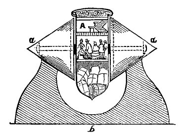
| Passenger and baggage compartments. Dircks, Henry. Perpetuum Mobile, 1861, p. 343. Phin, John. The Seven Follies of Science, 1906, p. 64. Schäffer, C. Naturparadoxe, 19ll, p. 44, fig. 22. |
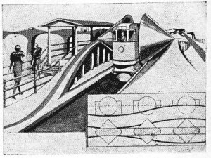
Arriving at station, with side and top view of tracks. Mann, Dr. Herbert: "Geschichtliches über das Perpetuum Mobile" in: Wissen und Fortschritt, 1930, p. 265, fig. 2. Michal, Perpetuum Mobile, 1971/76, p. 132, fig. 91. |
|---|
The fanciful picture on the right seems to be based on the same idea, but the illustrator seems not to understand the supposed principle of operation. It shows a cone-car arriving at a railway station. At the lower right are side and top views of the tracks. This inset shows the center of mass of the cone moving on a level. If this were so, the ride would be comfortable, but friction at the rails would make it a short ride. The figure labeled (b) shows the cone contacting the rails over a considerable length. This guarantees excess friction, and is simply poor engineering design, since not all portions of the cone move at the same speed. The only way for the car to gain kinetic energy on the diverging portion of the railway is for its center of mass to move down, as in the standard physics demonstration shown in the next pictures.
 |
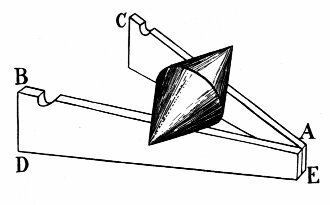 |
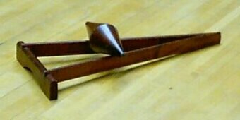
| Cone and rail demonstration apparatus. | |
|---|---|
The similarity of the original cone-car patent to this common physics demonstration apparatus is striking. The wooden rails actually slope, and a wooden cylinder placed on the rails will roll toward the pointed end. But the double cone placed on the rails will roll the other direction, because as the rails get wider apart, the center of mass of the cone is lowered.
Could the inventor have seen this demonstration, but failed to grasp the physics and geometry of it? They say that the student mind is like a blotter; it soaks it all in but gets it backward. Even clever physics demonstrations can be misunderstood, and can develop wrong concepts.
Thanks to Hans-Peter Gramatke for providing some pictures and verifying some of the German source references. You can see more of this sort of inventive creativity at his site: HPs technikgeshictliches Sammelsurium. Select the menu item "Bilderbogen".
Numerous books of strange and humorous patents have been published, and several websites feature generous collections of them. Hans-Peter has shared with us his favorite links.
- Patent of the week.
- Patently absurd inventions.
- Weird and Wonderful Patents.
- Patscan's bizarre patent page.
![]() Contributions of pictures and descriptions of unworkable devices
are always welcome. Send to the address shown to the right..
Contributions of pictures and descriptions of unworkable devices
are always welcome. Send to the address shown to the right..
Return to the Main Gallery of the Museum of Unworkable Devices.