|
Cranks keep the wheels turning. —Charles Fort |
Those who think this way are much like the child who puts two blocks in a
box, closes the box, shakes it, then opens it, hoping to find three blocks
inside. The child hasn't yet had sufficient experience with how nature
works to realize that nature doesn't work that way. Perpetual motion
machine seekers hope that by using some new combination of well-known
materials and well-known mechanisms, they just might make a machine
that outputs more work than is required to run it.
We can test its stability by turning the wheel to any position whatever. No
matter what position it happens to be in at rest, it has no tendency to
turn in either direction, and will not initiate motion by itself.
Contents
Principles of
Perpetual motion machine inventors do have principles. Unfortunately the
physical principles they assume are often ones not obeyed by nature.
Let's examine just a few.
Unworkable Devices.
Anything is possible
Inventors assume that since we haven't looked at every part of the universe
nor have we looked at all possible mechanisms or phenomena,
we can't rule out anything. If one has faith in oneself, perseverance, and
tinkers long enough with new and untested ideas, one may discover ways to
thwart "known" laws of physics.
The "heavier on one side"
seduction.
The most naive level of perpetual motion seduction is the notion that if a
system has more mass on one side of the axle, then that side must swing
downward. That notion is quickly dispelled by consideration of this
symmetric arrangement of three equal mass balls on equal length arms.
Clearly there's more mass on the left side of the axle. But just as
clearly, the device will not turn of its own accord. Even worse, if given a
push, it will not turn continually. It will come to a stop from dissipative
forces just as any wheel would. This wheel is as likely to come to rest in
one position as in any other, for it is perfectly balanced in any position.
Persons who have little experience with mechanisms may think it would prefer
to come to rest with one ball directly above the axle, and the other two
below. That is not true. Our naive expectations are not the way nature
works.
 |
The earliest unbalanced wheel of Bhaskara underwent countless modifications and embellishments over centuries. But the seductive principle that motivated the inventors was that "If you can keep the wheel continuously heavier on one side as it rotates, then it will continue rotating with constant speed forever." Their overbalanced wheels had weights that moved, and in the static picture at least, there were always more weights on one side of the wheel axle. But, when the system is analyzed, one finds that the torques are balanced (add to zero). A wheel will not initiate motion unless the torques are greater in one direction than the other. If the net torque about an axis are zero, the system will not start turning by itself.
The situation is worse than that. Newton's third law ensures that all internal forces in a system sum to zero, and all internal torques do also. If the system is to move, some external source must supply force or torque. A system with unbalanced torque from external sources moves toward a position where the torques will become zero. That's a position where the system will be in static equilibrium. Typically the system will oscillate around that position, slowing down gradually to rest as its initial stored energy dissipates and it comes to rest.
Critical readers will note that the above comments assumed a uniform gravitational field. Actually the gravitational field decreases with height, and the field direction diverges from the center of the earth. These effects are negligible for a machine that would fit in a laboratory. But they would cause a slight preference for one position of this wheel (which one?). Still, they won't provide any force that would cause a consistently preferred direction of motion through many cycles.
The "more weight on one side" distraction.
 Many people confuse 'mass' and
'weight'. To illustrate how this distracts some perpetual motion machine
inventors, consider the simple example analyzed by Simon Stevin. A
continuous chain of balls rests on an asymmetric ramp. Some persons
naively assume that the chain will turn continuously because there is
always more mass to the left of the vertex than on the right. But the
chain doesn't budge.
Many people confuse 'mass' and
'weight'. To illustrate how this distracts some perpetual motion machine
inventors, consider the simple example analyzed by Simon Stevin. A
continuous chain of balls rests on an asymmetric ramp. Some persons
naively assume that the chain will turn continuously because there is
always more mass to the left of the vertex than on the right. But the
chain doesn't budge.The inventor may even test his assumptions by removing the two balls resting on the right ramp and weighing them on a balance. He does the same with the four balls on the left. The weights are not the same. He says, "I have tested this experimentally, and the weight of balls on the left of the vertex is twice as great as the weight of the balls on the right."
But this isn't a valid test. By removing balls for weighing, he's removing them from the parts of the system they interact with, and thereby changing the geometric and physical relation they had with each other and with the ramps.So the inventor says "I'll prove my assertion that the left side is heavier by another method—experimentally." He places a fulcrum to support the system, directly beneath the top vertex of the triangle, so the fulcrum supports the entire system. The system tilts. "See, the system is heavier on one side!", he says, triumphantly.
"And if you still are not convinced," the inventor says, "I'll prove my assertion with another independent experimental test. I will put an electronic scale under the left corner of the ramp, and another under the right corner, to see which weighs more. As you can plainly see, the scales indicate different weights, proving that one side is heavier."
These last two tests are irrelevant to the inventor's purposes, for he is weighing the balls and the ramp. The mass of the ramp and the distribution of mass in the ramp is irrelevant to the operation of the machine, even the sort of operation that the inventor assumes."What about torques?", the skeptic asks. The inventor replies, "The loop at the bottom is obviously in balance, so we can ignore it." The balls on the left provide greater torque with respect to the vertex than do the ones on the right. There's an unbalanced counter-clockwise torque on the system, and that will produce counter-clockwise motion.
|
But, during all these tests on the actual system, the balls sit there unmoving. The inventor rationalizes: "If I could only get rid of that pesky friction, I'd have this thing running. Just a little more work tweaking the design, and it will sustain its motion forever."
What's the error here? When analyzing a system or a part of a system, one must consider all of the forces and torques acting on that part of the system. Yes, the torques due to gravity acting on the balls are unbalanced about the upper vertex. But other forces also exert torques on the balls. The reaction forces of the ramps exert forces on the balls. The tension in the links joining the balls is a consideration, too. When all these things are considered, we find to our dismay that the net torque on any part of this system is zero. More to the point, the net forces and net torques on the ball-chain are zero. So the chain doesn't move by itself.
By the way, if you think that trick of balancing the system with a fulcrum, or with the two balance-scales, is absurdly blatant, let me tell you that a perpetual motion machine inventor very recently (in 2002) tried to pull that very trick on me. But he honestly and seriously thought it provided conclusive evidence in favor of his hypothesis. I provide another example below in the Experimental "gotchas" section.
The "unbalanced torque" deception.
Some inventors realized that it's not enough to have more mass on one side of the axle. So they sought some way to keep the torques unbalanced as the device rotated. Several possibilities occurred to the restless minds of diligent inventors:
- Continually move mass from one side of the axle to the other just fast enough to replace mass lost elsewhere by the turning of the wheel, but accomplish those transfers without doing work on the mass from any external energy source.
- Keep some part of the mass continually on one side of the axis, even as the wheel turns, so the wheel remains unbalanced.
- Introduce some force that is always greater on one side of the axle than the other, which provides torque that is continually greater in one direction of motion.
- Shield some portion of the machine from external forces.
 Attempts to transfer mass run up
against a cruel fact of nature. Even in the absence of friction
the work required to take a mass from point A to point B and back again is
exactly zero, and all wheel machines move masses around closed loops.
Also, it takes the same amount of energy to transfer
mass from A to B in a gravitational field no matter what path you choose
between those points.
Attempts to transfer mass run up
against a cruel fact of nature. Even in the absence of friction
the work required to take a mass from point A to point B and back again is
exactly zero, and all wheel machines move masses around closed loops.
Also, it takes the same amount of energy to transfer
mass from A to B in a gravitational field no matter what path you choose
between those points.
Consider the simple wheel shown. If it rotates clockwise, moving the light blue sector at the top to the right of the axis, the same size sector at the bottom moves to the left of the axis. The net result is that the mass distribution of the wheel remains the same as before.
The sector at the top has greater gravitational potential energy than the one at the bottom, so the inventor is encouraged. But then he discovers that the top sector loses exactly that amount of potential energy as the wheel rotates it to the bottom, while the sector at the bottom gains the same amount, for a net energy change of zero. Drat!
The nature of the gravitational field is at fault. Nature insists that the net amount of work done in carrying a mass around a closed loop in a gravitational field be exactly zero. (The same is true for electric fields.) Such fields are called "conservative" meaning "energy-conserving". There are advanced mathematical ways of saying this, using vector calculus, but that goes beyond our present needs or purposes.
 |
| Pierre Richard (Engineer, Paris), 1858, British patent No. 1870. Dircks (1861), p. 482. |
|---|
The clever deception shown here looks like a deliberate satire/parody, and a challenge to discover the built-in jokes. But it was patented. The patent examiners didn't "get" the joke. Its essential principle is that the chain of heavy balls nest in cups attached to the outer wheel, but only on the right side, providing considerable clockwise torque to the wheel. The vertical portion of the chain passes through the rotation axis, so those balls provide no torque about that axis.
The inventor has included a brake on the left. Some inventors included a brake as an obvious joke "to keep the machine from running so fast it would tear itself apart." This picture has an artistic deception. The two spokes at the top of the wheel are behind the solid frame of the machine, but the other spokes are in front of it. Therefore if anyone or anything tried to turn the wheel, the spokes would hit the frame, preventing further motion.
The lower pulley has no obvious support. Also, it seems non-functional and could be omitted without compromise of the machine's performance. The upper pulley also has no apparent support, but a pillow block on the upper frame would fix that. The spokes should be behind the plane of the wheel so they don't interfere with the ball-chain, and the upper pulley could easily be supported by another frame on the near-side of the wheel. The cups should be designed with a slot to accommodate the short links between the balls, and their tilt optimized so the balls won't slip out of the cups near the top, and so the balls will release without impediment at the bottom. Any competent mechanical engineer could fix all of this. All of these mechanical and artistic "flaws" are mere window-dressing, and probably the fault of the artist, not the inventor. Yet some people will focus on them and declare triumphantly that they have discovered the reason the device won't work, while missing the real reason.
It seems that there's always a net clockwise torque on the wheel—of considerable size. But there's a hidden torque balancing that, provided by the weight of the vertical portion of the chain. This torque is exerted on the outer wheel just above the top pulley. It arises from the tension in the chain. The balls aren't supported entirely by the cups, but partly by the tension in the chain.
This is one of the most ingenious deceptions in the PMM literature.
The cyclic disappointment
|
Machines are cyclic. Wheels turn around an axle. Any process intended to produce power must move its components cyclically.
Many of the previously noted delusions about nature have the common feature that they are based on true observations about how something behaves over a finite time and distance (such as a ball rolling down an inclined plane) then assuming that such a process can also be worked into a wheel or other cyclic device. The trouble is, that with a cyclic device:
- The weight that gains energy falling on one side of a wheel must lose the same amount of energy when being lifted up the other side.
- The steel ball attracted to a magnet gains energy, but to return it to its original position and repeat the process, at least that much energy must be given to it.
- A buoyant object rising in water gains energy, but it takes at least that much work to return it back to its starting point at the bottom in order to repeat the cycle.
- A charged body in an electric field can be set in motion, gaining energy. But to return it to its starting point requires at least that much work.
So, how about a non-cyclic machine? Can a ball roll down an incline forever? You'd need an infinite length incline, and a gravitational field of infinite spatial extent. All fields known in the universe have two features that make this impossible: (1) they have "sources" at a particular location in space, and (2) their strength decreases with distance from the source, becoming zero at infinity.
To make a gravitational field nearly uniform over a large region of space would require a distribution of mass over a volume of space as large as that region. To assemble and "nail down" that much mass requires a huge expenditure of energy. Finally, the energy available to any machine operating in that field is no greater than the energy you expended in assembling that mass to produce the field.
To increase the size of that uniform region to infinite extent requires an infinite amount of mass, and where do you put that mass? We are forced to make do with cyclic processes occurring in a relatively small finite region of space.
Ultimately the common feature underlying all of these natural limitations, and underlying all of physics, for that matter, is geometry of space and time.
The elastic/inelastic dilemma
When we analyze perpetual motion machines, it's useful to begin by idealizing the system, assuming zero friction. If the machine won't work as we hope without friction, it surely will perform worse with friction. But what about other energy-dissipative processes that convert mechanical energy irreversibly to thermal energy (heat)? Can we treat them the same way?All real materials deform to some extent under application of force or pressure. In fact, one can argue that perfectly rigid bodies are a physical impossibility because then impacts between such bodies would give rise to infinite reaction forces for infinitesimal time durations.
In many materials, such as steel and glass, collisions can be over 95% elastic, that means that less than 5% of the impact energy is dissipated irreversibly. Can we assume elastic materials in our initial analysis, confident that this will set an upper limit on a machines efficiency?
If we do so, we encounter a serious dilemma. Consider any machine that has rolling balls, or shifting weights that suddenly change velocity due to impacts. Many classic perpetual motion machine designs have swinging hammers suddenly hitting pegs or "stops", as in Villard's wheel. Others have balls rolling down inclines and then stopped suddenly. Whenever there's such an impact, the hammer or ball will bounce or rebound. Invariably the inventor has not taken this fact into account, and it always decreases the assumed performance of the machine.
So can we redesign the machine for "softer" impacts? Perhaps we can put cushioning material at the impact point, or some sort of a catch or latch to prevent rebound. Alas, this is worse, for any such cushion or latch makes the impact inelastic, and dissipates energy as heat or sound. [In fact, chatter, clatter, whirring, humming, ticking or banging sounds from a machine are a sure sign of irreversible energy dissipation—meaning the machine is losing energy. The perfect perpetual motion machine would necessarily be perfectly silent.
|
It is not generally appreciated, even by some physicists and engineers, that a collision or impact can involve very nearly elastic materials and still be a significantly inelastic (energy-dissipating) impact. An elastic material is one that can be slowly deformed, then relax to its original state without energy loss due to the deformation. But during a rapid deformation due to collision or impact, energy is temporarily stored (as elastic or vibrational energy) within each body, and when the bodies separate, one or both of them may still retain some of that stored energy, which is subsequently slowly dissipated as sound or heat as the body vibrates. Think of a bell being hit by a clapper. The bells are made of elastic metal, but they release energy as sound long after the imapact is over.
These phenomena are yet another "gotcha" nature springs on the over-optimistic perpetual motion machine inventor. Whenever the mechanism of a machine involves changing accelerations (and what mechanism doesn't?), mechanical energy will be dissipated irreversibly. But, as with friction, if we idealize these for analysis and the machine still won't work as we hope, then it will perform even more poorly with real materials and machinery. If we idealize everything and the machine's efficiency is still less than one, then we haven't achieved perpetual motion.
Generally we avoid bringing up classical thermodynamics, but here we can't resist mentioning the implications of what we've said above. One statement of the second law of thermodynamics tells us that the efficiency of a cyclic engine can never exceed that of a Carnot engine operating between the same two temperatures. A Carnot engine is an hypothetical "ideal" and "perfect" engine, assumed for comparison purposes. No one could ever build one. The efficiency of a Carnot engine depends on its input and exhaust temperatures, according to the formula e = 1 - (Tc/Th), where Tc is the kelvin temperature of the cold reservoir and Th is the kelvin temperature of the hot reservoir. (The kelvin temperature scale begins at absolute zero.) For real engines this efficiency is much less than one, only approaching a value of one when the temperature difference between output and input becomes infinite.For example, the Carnot engine cycle is shown here for an ideal gas, on a pressure-volume-temperature graph. Everything about the Carnot engine is idealized, to properly represent the upper limit of what's attainable. The gas is an ideal gas, in which all gas particle collisions are perfectly elastic. The cycle has two portions during which the gas expands and contracts along isothermal (constant temperature) paths on the graph. It has two portions where, thanks to perfect insulation, the gas expands and contracts along two adiabatic lines (no thermal energy loss or gain). (T1 and T2 are the temperatures of the cold and hot reservoirs, while A1 and A2 are adiabats.) The changes occur infinitesimally slowly, to avoid inertial effects.
Real engines, if they are to be any use, must complete a cycle much faster, so inertial effects are unavoidable. Therefore the path (on this graph) of such a real engine will have "rounded corners" and will lie completely within the path of the Carnot engine. By the definition of work, it can be shown that the work done by engines is proportional to the area within their closed path on this graph. Therefore the real engine will do less work than the Carnot engine operating between the same temperatures, since its area is within that of the Carnot.
The Carnot engine's efficiency is proportional to the area within this boundary (the sum of the light blue and dark blue areas). Compare the diagram for a real heat engine (the smooth closed curve filled with light blue) operating between the same two temperatures, and you see that those sharp corners of the graph are rounded off, and the area within this curve is smaller. The efficiency of this engine is therefore smaller. While the ideal engine for other sets of variables will be different, the same general conclusions apply.
The Carnot engine has greater efficiency than any other engine operating between the same temperatures. If we idealize everything in a device and its efficiency still isn't greater than that of a Carnot engine operating between the same temperatures, then the second law of thermodynamics is still secure.
Textbooks always stress the point that the Carnot engine operates with strictly reversible processes. But sometimes they don't sufficiently emphasize that the operation of the Carnot engine requires infinitesimally slow operation, to avoid infinite accelerations of its material components. One method of analyzing the entropy changes in a real engine is to decompose its operating cycle into an infinite number of infinitessimal Carnot cycles. This is a valid method, but doesn't eliminate this problem—it only disguises it.
Even in the realm of smaller materials, atoms, molecules, and electrons, similar "gotchas" arise to thwart inventors' aspirations.
Failure to isolate the system
Freshman physics students are continually admonished to "isolate the system" when calculating the sums of torques and forces on a system, or some part of the system. Failure to do this leads to seriously wrong conclusions. The net force on a system is the sum of external forces acting on that system and only forces acting on that system. For purposes of analysis one may choose some portion of a machine as the "system", but must be careful always to keep in mind exactly what that portion is.
This simple machine has been constructed to illustrate such errors with a minimum of complicating details. In fact, this picture is the essence of the idea behind hundreds of perpetual motion machine proposals of the 17th and 18th centuries, which were often fantastically Baroque in their embellishment of mechanical details.
A wheel is free to turn on axle A. A heavy mass M is fastened to an L-shaped member MXY, hinged at pin X near the edge of the wheel. Point Y is linked to a member YZ that has the same effective length as AX.
The inventor points out that there's obviously more mass on the left side. Clearly if the machine were in this position and then released, the wheel would turn counter-clockwise as the mass M moves downward along the dotted line. The only path this mass can take is the dotted circle, which is entirely on the left of the axle A. So the mass always provides a counterclockwise torque anywhere on this circle. Also, wherever the mass is along this circle, the mass is greater on the left of the axle.
The inventor thinks he has solved the problem of keeping the mass and the torques unbalanced as the wheel turns.
This drawing is unlikely to deceive anyone, for the error is right out there for anyone to see. But the same fundamental deception is at the heart of many machines seen in the perpetual motion machine literature, but in those machines the deception is buried in a mechanic's nightmare of wheels, belts, linkages, springs, and other distractions.
The give-away here is the fact that the mass M must rise as high as it falls, so the net work done on it by gravity is zero around one cycle. But if the inventor focuses attention on the torques, some people may be seduced into thinking that the torques are unbalanced at any position of the wheel. How can that be?
 |
| John Haywood (Br. mechanic), 1790, British patent No. 1750. Dircks (1861) p. 66. |
|---|
The torque due to gravity on the mass M, about the axle A, is always counter-clockwise in this machine. But that's not the only torque acting on the rigid combination of mass M and the member MXY. At point Y there's a force due to tension in member YZ, and it is clockwise around the axle A. There's also a force that the wheel exerts upward at joint X, and that also gives a clockwise torque around A. Now when the mass M is rising after it reaches its lowest point, the sense of these torques due to forces at X and Y changes sign. The net torque on MXY during the fall is counter-clockwise, while the net torque during the rise is clockwise. The torque analysis gets a bit messy, but the bottom line is that the net work done by all of these torques acting on member MXY is zero during each cycle.
The machine shown on the right was invented by John Haywood, a draftsman and mechanic. He obtained a British patent for it. The small rollers at the end of each spoke are supposed to be quite heavy, to provide the "overbalance". The error of physics that led him (and the patent examiners) to think it might work is the same as in our simpler machine described above.
The static/dynamic trap
Inventors who do appreciate the importance of torques will sometimes carefully analyze the torques in their proposals, concluding that the torques are unbalanced. This can result when they have drawn the picture in a manner that contradicts their assumptions. They draw, and analyze, a static picture of an unmoving wheel, and use the results to draw inferences about a rotating wheel. Sometimes they do it the other way around. If the wheel has shifting weights (as most have), their drawing shows at least one weight in a position it could not be in if the wheel were in the assumed state of motion.The classic overbalanced wheel is such a case. As shown here it's easy to calculate the torques due to gravity acting on each of the balls. It's a correct static picture of one of the resting positions of the wheel. But is it a correct snapshot of the wheel in motion?
 |
 |
 |
We should always be suspicious of computer animations, for while they look impressive, they may very well be constructed on mathematical models the programmer assumes, but which may not be the ones that nature uses. This animation of the overbalanced wheel is unphysical in several respects. Can you identify its errors?
Answers left as an exercise for the reader.
The apples/oranges conversion
Physics is structured in such a way that the units and dimensions of quantities help prevent blunders. Most students know the rule that quantities with different units are never added. It follows that they aren't equated either. But students forget this, and sometimes incorrectly assume that angular momentum and linear momentum are two varieties of the same thing. Some perpetual motion machine inventors have sought to convert angular momentum to linear momentum. Some try to 'convert' momentum to energy. They fail. Some seem to think that forces and torques can be equated, or even equate force and work. One even told me that work and torque are the same thing because they both have units that are the product of force and distance. Here's an example. A system consists of
three pulleys, R1, R2, and R3 and a flexible belt. Pulleys R1 and R2 are
very heavy, while R3 can be lightweight. The whole system is hung from
support S. The function of R2 is supposed by the inventor to provide
continuous unbalance of the system. The inventor thinks that this makes the
system "heavier on the right side" and therefore the belt will
turn clockwise.
Here's an example. A system consists of
three pulleys, R1, R2, and R3 and a flexible belt. Pulleys R1 and R2 are
very heavy, while R3 can be lightweight. The whole system is hung from
support S. The function of R2 is supposed by the inventor to provide
continuous unbalance of the system. The inventor thinks that this makes the
system "heavier on the right side" and therefore the belt will
turn clockwise. The inventor, still unconvinced, tests his
assertion of heaviness with the system shown to the left, using two spring
balances S1 and S2 and a bar B on a fulcrum that allows the bar to tilt.
He observes that S2 indicates larger force than S1 and the bar tilts down
on the right. "This proves that the right side is heavier," he says.
The inventor, still unconvinced, tests his
assertion of heaviness with the system shown to the left, using two spring
balances S1 and S2 and a bar B on a fulcrum that allows the bar to tilt.
He observes that S2 indicates larger force than S1 and the bar tilts down
on the right. "This proves that the right side is heavier," he says. We are now dealing with the real
world of real materials, not the idealized world we sometimes assume for
initial analysis of perpetual motion machine puzzles. As the offside weight
R2 is allowed to rest against the belt, the belt bends there until its
reaction force is sufficient to bring the system to equilibrium. The belt,
however, isn't perfectly flexible, nor is it frictionless. Friction and
elastic deformations of the belt may supply forces that prevent the
pulleys from assuming their smallest potential energy. Good lab practice
requires fiddling and jiggling the system to find the range of
positions the system can assume and still be unmoving. However, if the
initial measurement confirms what the inventor expects, he may have no
motivation to do that.
We are now dealing with the real
world of real materials, not the idealized world we sometimes assume for
initial analysis of perpetual motion machine puzzles. As the offside weight
R2 is allowed to rest against the belt, the belt bends there until its
reaction force is sufficient to bring the system to equilibrium. The belt,
however, isn't perfectly flexible, nor is it frictionless. Friction and
elastic deformations of the belt may supply forces that prevent the
pulleys from assuming their smallest potential energy. Good lab practice
requires fiddling and jiggling the system to find the range of
positions the system can assume and still be unmoving. However, if the
initial measurement confirms what the inventor expects, he may have no
motivation to do that.
|

This principle is sometimes called the "Baron Munchausen" principle after the 18th century teller of tall tales. He said he got of a desperate situation by grabbing his own pigtail and lifting himself up from a quagmire. (Some derivative tall tales have one lifting himself by his bootstraps, the origin of the term "bootstrap princicple".) Use of this trick is one example of an inventor's ignorance of (or disdain for) well-known valid physical principles.
 |
A simple example is the old joke or cartoon in which someone in an automobile uses a fishing pole to suspend a large magnet in front of the auto, thereby causing the auto to be pulled forward by the magnet. Nature doesn't work that way. Another example is the ice-boat with sail. Trouble is, there's no wind. So a fan in the back of the iceboat is turned on, blows air at the sail, and the boat moves briskly forward. (This joke was featured in the sci-fi movie "Barbarella." Some folks in the audience didn't get the joke.) Several PMM proposals use this idea, but bury it in distracting mechanical details. One is Chris Cheng's magnetic engine, where the magnetic shield, which supposedly causes the unbalanced force on the magnet, moves along exactly as the magnet moves. Unfortunately, neither of them move.
Hans-Peter Gramatke contributes this elegant design to our museum that takes advantage of the "dog chasing its tail" principle. The magnet at the front of the car pulls on the steel anvil, moving the car forward. When the driver wishes to slow or stop the vehicle, he pulls the lever that rotates the magnet to a less effective position. Then he may apply the brake.
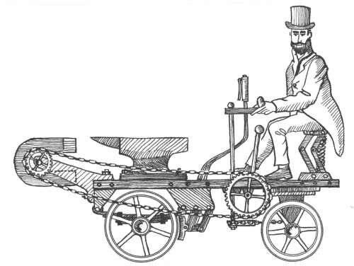
Critics may argue that with the linkage shown, a person wouldn't be strong enough to rotate the magnet to stop the car. The engineering "fix" for that is simple. Use a clutch that allows some power from the front wheels to assist the turning of the magnet.
In Gardner D. Hiscox's classic book, Mechanical Appliances and Novelties of Construction (Norman W. Henley Publ. Co. 1927) we find in Chapter23 a machine that uses the power of a waterwheel to drive a pump that lifts the water to the top of the wheel. This delusion is as old as waterwheels themselves, and Hiscox demolishes the idea elegantly:

Water wheel and pump, an...often repeated type. A principle so often employed for the production of self-moving machines that it ranks next to that of perpetual eccentric weights in its delusive power upon the minds of inventors. The attempt to compel a water wheel to raise the water which drives it is in one form or other perpetually recurring in devices upon which our counsel and opinion are sought.The worst of the matter is that in most cases our advice to drop such absurd projects is received as evidence of want of sagacity and knowledge, and our would-be client becomes the dupe of some not over-conscientious patent agent, who pockets his fees and laughs in his sleeve at the greenness of the applicant.
The device illustrated is one submitted by one of those enthusiastic individuals, who, without understanding the first principles of mechanics, believes he is about to revolutionize the industry of the world by his grand discovery; and as honor, and not pecuniary reward, is his object, he seeks to make public his invention through the wide circulation of some journal. He is quite willing we should adversely criticise the device, because its merits are so great that no amount of skepticism resulting from our blind prejudice can, he thinks, influence candid minds against a principle so obviously sound and sublimely simple.
|
Even if you could completely eliminate friction and viscosity in the pump and gears, this device requires the pump to lift water above the open reservoir, that is, higher than the pressure head of the reservoir, requiring more work than one can gain from the falling water. Even if that minor (!) flaw were fixed, the work done in carrying the water around a closed loop is zero. Exercise for the student: If viscosity and friction were zero, and this device were primed and started running, how and when would it come to a stop?
Reinventing the square wheel
|

It's amazing how many proposals we get that turn out to be minor variations of ideas proposed centuries ago, whose errors have already been exposed, and which have never worked. Not only are many inventors innocent of fundamental physics and engineering principles, they seem unaware of the long history of failed attempts at perpetual motion and the reasons for those failures.
Engineering art has produced many "standard" mechanisms that, singly, or in combination, have proven to be functional and successful for their intended purpose. Perpetual motion machines have mechanical features different from those of familiar and useful machines. The inventor hopes that such novelties of design may produce novel results. But the result is invevitably a failure.
Return to front page.
Return to the top of this document.
Return to The Museum's Main Gallery.