Analysis of the power amplifier fallacy.
 |
 |
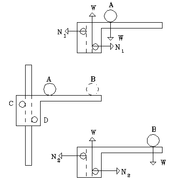
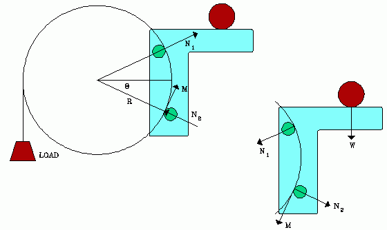
| Free-body diagrams of the platform on a pole. | The complete apparatus: drum, platform and load. |
|---|
Discussion
The simple resolution to this mess is in fact the obvious one, the one that experienced physicists and engineers would see immediately: If, as the inventor assumes, the weight on the platform is kept from moving by the motor, then the platform and the weight on it do no work on any part of the system. Also, no work is done on it. This is true wherever the weight is placed on the platform. Work is the product of force and distance. No force, no work. No distance moved, no work. The position of the mass on the platform does not contribute in any way to the work output. Case closed.
Then why does the idea look appealing to some people, including the inventor? I'm reminded of a problem students often have understanding work. Suppose you hold a heavy weight in your hand, taking care to keep it stationary. Are you doing work on the weight? No for it doesn't move. Are you doing work on anything? Yes, you are doing work through the continual almost unnoticed contraction and relaxations of muscles under tension. These are microscopic level processes. Internal forces in your body do this work, which is dissipated as thermal energy within your body. None of this work represents net mechanical work acting on the weight you are holding.
Any feedback system, biological or mechanical, does the same thing. So whatever feedback system we use to control the motor speed, the motor is expending work of this sort as it keeps the platform stationary. But none of this work contributes anything at the output of the machine (lifting the load at the left).
A related situation occurs when you push against a wall, causing your body to accelerate away from the wall. Does the wall give you that acceleration? The external force of the wall acting on your hands is responsible for your acceleration. Does the wall do work on you? No, the force acting on you does not move through a distance. Do you do work on the wall? No. the Wall does not move. Internal forces do the work that changes your kinetic energy. But internal forces cannot change a body's momentum. It is the force of the wall on your hands that changes your momentum. This sort of problem is found in some textbooks to make a distinction between real work and pseudowork, and between internal work and work done by external forces. But let's see if we can avoid that here. (However, if some reader would like to submit a discussion of this PMM in terms of pseudowork, we'd like to see it.)
But our inventor may still not be satisfied. He has argued that the platform exerts a torque on its supports, and that torque must depend on the position of the mass on the platform. So doesn't that torque get communicated to its supports, and shouldn't the reaction forces between platform and drum exert a torque to turn the drum? Let's pick this argument apart by examining its "logic".
Look at the first drawing, of the platform on the pole. If the platform is not accelerating, the net force on it must be zero. This is true for the platform at rest, or even if it is moving with constant speed up or down the pole. At the upper right is a free-body-diagram (FBD) showing all forces acting on the platform. The idler wheel exerts only a horizontal force, for it is free to rotate, and we assumed it was frictionless. However, the gear driven by the motor experiences a force from the rod that has both vertical and horizontal components, for it is a gear on a rack. However, the only two horizontal forces are N1 and N2. These must add to zero, so they must be of equal size and opposite direction. There are only two vertical forces acting on the platform, so we show them as of equal size W, with opposite direction.
What happens if we move the weight from A to B? The forces N1 and N2 both increase, but will still be equal in size, for there's no horizontal motion. The torque on the pole does increase, but that does not affect the force the motor must supply to move the platform up the pole. That force is still W, wherever we place the weight on the platform.
Now our inventor assumes that we can transfer that torque to a drum if we let the platform, with its motor, ride on the right side of the drum as shown in the second drawing. I have seen this mistake before. Students often memorize laws and principles without understanding. So they "reason" thus:
- Newton's third law says that if body A exerts force on body B, then B exerts and equal and oppositely directed force on A.
- Since torques are associated with forces, then if body A exerts a torque on B, then B exerts an equal and oppositely directed torque on A.
- Therefore extra torque on the platform can give that extra torque to the drum.

|
The color figure shows what's really happening. We have exaggerated the size of the angle between the rollers for clarity. The first step in analyzing a system is to draw the FBD diagrams for its parts. At the upper right we have the FBD of the platform with all forces acting on it. Note that the forces N are not parallel here, but are along lines passing through the center of the drum. This is the nature of forces at the contact between two surfaces of different radii (the drum and the rollers). The reaction forces to the Ns, acting on the drum, also necessarily pass through the center of the drum. These forces are incapable of exerting any torque on the drum. They are the only forces that the platform exerts on the drum.
The position of the weight on the platform does affect the forces, N. Moving the weight to the right increases both of these forces, but their horizontal components still add to a vector equal and opposite to the horizontal component of M. However, as we saw, they cannot exert a torque on the drum in any case. The only thing that can exert a torque on the drum is M, exerted by the driving gear. The position of the weight on the platform has no effect on M. This last assertion may not be obvious at first look, but we leave it as an exercise for the reader to prove it. It's really quite a simple proof.
The inventor may also have been seduced by his failure to draw the diagrams as we have. He may have assumed that because in the first example the platform exerts a torque on the rod that is dependent on the position of the mass on the platform, that the same will be true when the platform is affixed to the drum. But geometry did him in, for a drum is a circle, and a rod is a straight line. The forces N on the rod are parallel, forming a couple, exerting a torque on the rod. But the forces N on the drum pass through the center of the drum, so they exert no torque on the drum, and do not constitute a couple.
But the fallacy may also have something to do with fallacy of my little car on the conveyor belt. That example has no drum. We leave this also as a chance for the reader to have some fun doing free-body-diagrams and using Newton's laws.
Mistakes students make.
Students often find problems of this sort difficult, and make many errors in analyzing them. These errors are so common that instructors use the abbreviation FBD when marking papers, to indicate that one of these errors was made. So it's worth listing them here.- Failure to even draw the free body diagrams.
- Omitting forces from a free-body diagram.
- Forgetting that for each diagram, only forces acting on that body are included. Students often include a force that acts on some other body.
- Assigning the wrong direction to a force.
- Mishandling reaction forces at surfaces. If body A exerts force at B, then B exerts and equal size and oppositely directed force on A. Check all FBD for consistency.
- Forgetting to include the force due to gravity (the weight).
- When a torque analysis must also be done, the vector representing the weight of a body must pass through the center of gravity of that body.
- When a torque analysis must be done, reaction forces may vary in size and direction over interface surfaces. They must be summed properly by a calculus process, and the sum vector must be located properly as well. This is a point that should be carefully studied in a good textbook.
- A zero force does no work.
- If there's no displacement of the body, no net work was done on it.
- If the angle between the force and the body's displacement is ninety degrees, that force does no work on that body. (Equivalent: If the force has zero component in the direction of the body's displacement, that force does no work on that body.)
A related problem.
Some years ago I gave an exam question about this little car on a conveyor belt. It went something like this:
This sort of question has long been used in mechanics courses in colleges and universities, and even in graduate school oral exams, to expose student misconceptions. Sometimes it is used to motivate a discussion of real work and pseudowork, but there are simpler examples of that. It is very easy for someone who understands the principles of mechanics, but those who don't will fall on their faces trying to explain it. Students must do the free-body-diagram analysis of the components of the system to properly understand it.The red car is on the conveyor belt C, causing it to turn the drum D which lifts the weight W. The car adjusts its speed so that the car moves neither up nor down, but just stays at a constant position. (Compare a person on an inclined treadmill.) An additional weight (green ball) can be placed on top of the car, either at A or B. When placed at A it has greater torque (moment), about twice as great, about the center of the drum than when it is placed at B.
a) Draw the free body diagrams for forces and torques for car, conveyor, drum and weight. Suppose that there are no dissipative energy losses anywhere in the system. Does the car do work on the conveyor belt? Does the conveyor belt do work on the car? What is the work done on the weight? Discuss the torques on each body. Do this for both positions of the green ball.