Surely they can't be serious?
Some perpetual motion designs show great ingenuity and planning. Others are just plain "dumb". Here are some in the latter category, presented with minimal comment. Most persons immediately realize they couldn't work, just from everyday experience with machines, even without sophisticated analysis. Though they seem so obviously wrongheaded, it's still a challenge to coherently explain what, specifically, is wrong with them that prevents them from working as the inventor hoped.
 |
 |
| The kinky chain. Clearly there's more weight of chain on the right than on the left, so it should turn clockwise. [Hiscox, 919] | F. G. Woodward's wheel. A simple cylindrical wheel, B, supported by the rollers labeled C. Since allmost all of the wheel's weight is to the left of the supports it should turn counterclockwise as indicated by the arrow. [Hiscox, 934] |
|---|
Hint for both of the above. Do the force and torque analysis.
| Four arms are free to rotate. The weights A near the center weigh 25% more than the weights B near the ends of the arms, and are connected by an ingeniously designed levers, C. Gravity pulls down the central weights A, pushing the weights B leftward so that the left arm has greater torque (counterclockwise) than the torque of the right arm (clockwise). This should initiate and sustain counterclockwise rotation. If the inventor had put as much time into calculating forces and torques as he put into designing the lever linkages, he could have saved himself the trouble and expense of building this thing. And the artist failed to include the support for the upper linkage at "C". [Hiscox, 930] |
|---|
 |
 |
| This patented device is self-explanatory. The chain of heavy balls is clearly kept overbalanced, with not only more weight, but more torque on the right side. [Pierre Richard (engineer, Paris), 1858, British patent No. 1870. Dircks (1861), p. 482.] |
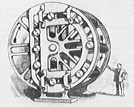
This device uses heavy rollers, guided by a fixed channel and by the spokes of a wheel. Is this the same as the one to the left? No, this one has equal weight at all times on either side of the axle, but the inventor supposes that the torques are greater on the right. A foolish supposition. [Science and Invention, March, 1925. |
|---|
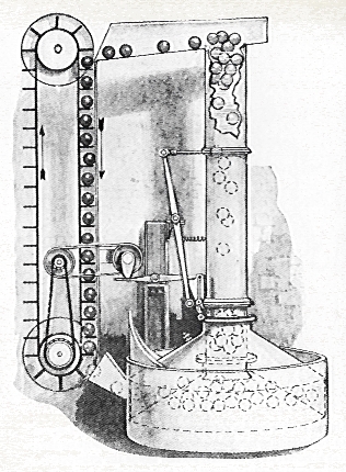 |
The hydraulic ball-machine. This artist's conception represents an idea patented several times. Balls lighter than water rise in the tank at the right, spilling over and then by their own weight drive a vertical conveyor belt at the left. Some "Rube-Goldberg" linkages control several levers that operate "magic" valves in the water column to control the rate of transport of the balls. An even more mysterious "magic" valve allows the balls to pass from the bottom of the conveyor belt into the water tank. [Science and Invention, March 1925.] |
|---|
 |
Compare this with the previous device. Since bubbles are naturally buoyant, why not inject air at the bottom of the wheel, which lifts the inverted buckets on that side, turning the wheel? The inventor tells us this will provide an unlimited source of "green" energy to power anything, even generate electricity. On the mistaken principle that "bigger works better" he suggests this be 66 feet high. I find these things an endless source of amusement. This one is about as interesting as an air pump generating bubbles and driving a waterwheel in a fish tank. The inventor says he has applied for a patent [in 2012]. Even if granted, this still will not achieve the inventor's dreams of over-unity performance. He overlooked several things that ought to be obvious. |
|---|
Of course none of these devices have over-unity efficiency. We haven't explained why in all cases, for the readers of my other web pages on this subject already know the reasons. We have more space for your own favorites. Suggestions welcome.
Return to Donald Simanek's front page.
Return to the Museum of Unworkable Devices Main Gallery.
Return to the top of this document.