Buoyancy
 Perpetual motion machine inventors are
fascinated by buoyancy, supposing that buoyancy has some "magical"
ability to produce motion against gravity without expenditure of
energy.
Perpetual motion machine inventors are
fascinated by buoyancy, supposing that buoyancy has some "magical"
ability to produce motion against gravity without expenditure of
energy.
Textbook treatments of buoyancy are usually based on Archimedes principle: "A body immersed in a liquid experiences an upward force due to the liquid, of a size equal to the weight of the displaced liquid." A more insightful (but equivalent) treatment goes like this:
Consider a body of mass m and volume V that is less dense than water. If it is pushed underwater and released, it moves upward. As it moves upward from position A to position B, water must move downward. The volume V at position A which the body occupied must now be replaced with water, and the water that was in the space it now occupies at position B must be displaced. The net effect is that as the volume V of the body moves from position A to position B, an equal volume V of water moves from position B to position A.
|
Whenver a mass moves in a gravitational field, work may be done on the body by the field or on the source of the field by the body. That work is of size Fh where F is the size of the force exerted on the body by the field and h is the distance moved vertically. When a body moves up in the field (opposite to the gravitational force) it does work on the source of the field. When the body moves down in the field (in the direction of the gravitational force) the source of the field field does work on the body.
We tabulate the force and work on the body (mass m) and on the equal volume of water (mass M). Since the body is lighter than water, m < M. The net work done on the body moving up in the liquid is (M-m)gh = (Mg-mg)h. We identify Mg as the size of the Buoyant force, and mg as the force due to gravity acting on the body of mass m.
Mgh is the work done by gravity on the water during the displacement downward. -mgh is the work done on the lighter body being displaced upward.
So we see that motion of a body in a liquid is just a motion of two masses exchanging positions in a surrounding liquid. Nothing mysterious here. Furthermore we can look at it in the light of Newton's third law. If the body m experiences a force due to the liquid acting on it, the liquid experiences an equal and opposite force from the body m acting on the liquid. It follows that the work done by the liquid on the mass equals the work done by the mass on the liquid. The only agent doing any other work on either of them is gravity.
In short, machines using liquids are just another example of shuffling masses around. The masses still obey Newton's laws, so you don't get something for nothing. It's even worse. Liquids introduce viscosity, which invariably reduces performance because it's an energy-dissipative process.
 The usual texbook presentation of this considers only forces on the submerged
object. The gravitational force mg acts downward.
g is the size of the acceleration due to gravity.
The buoyant force B acts upward. The net upward force is
B - mg.
From Archimedes' principle, the size of B is
B = r gV where
r is the mass density
of the liquid
and V is the volume of the immersed body. This is correct, but
it obscures the insight that when the immersed body moves up an equal
volume of liquid must move down. Perpetual motion machine inventors
very often forget to include that water motion in their thinking.
The usual texbook presentation of this considers only forces on the submerged
object. The gravitational force mg acts downward.
g is the size of the acceleration due to gravity.
The buoyant force B acts upward. The net upward force is
B - mg.
From Archimedes' principle, the size of B is
B = r gV where
r is the mass density
of the liquid
and V is the volume of the immersed body. This is correct, but
it obscures the insight that when the immersed body moves up an equal
volume of liquid must move down. Perpetual motion machine inventors
very often forget to include that water motion in their thinking.
Buoyant Wheels and Belts
 |
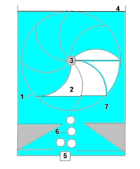
Here's a simpler-looking device operating on the same principle. It also operates underwater. The wheel has bellows with lead weights attached. The air in all bellows is shared through tubes in the eight arms to a chamber in the hub.
The inventor remembers Archimedes' principle from high school physics. It says that when a body is immersed in liquid the liquid exerts and upward buoyant force on that body of size equal to the liquid the body displaces." The "displaced" liquid is simply a volume of liquid equal to the volume of the body.
 |
So in these devices, the weights act to reduce the air volume in the pistons or bellows on one side of the axle, increasing the volume in those on the other side of the axle. Therefore the pistons or bellows on the side with increased volume experiences larger buoyant forces than those on the other side of the wheel. Therefore both of these devices should turn counterclockwise.
The buoyant forces on the lead weights are all the same wherever the weights happen to be. The buoyant forces on the cylinders, bellows and other parts of the system clearly balance. These arguments are very seductive to lead one to think these devices will turn continually.
 Consider this simpler arrangement of just two pistons. The buoyant
forces are labeled B1 and B2.
with B2 > B1. The gravitational
forces on both sides are equal, so this buoyant force unbalance should
cause the right side to rise.
Consider this simpler arrangement of just two pistons. The buoyant
forces are labeled B1 and B2.
with B2 > B1. The gravitational
forces on both sides are equal, so this buoyant force unbalance should
cause the right side to rise.
But will that motion continue around a complete cycle? The pistons must pass over to the other side of the wheel. The inventor has lulled us into complacency, directing our attention to the unbalanced buoyant force, so we are tempted to neglect what happens when "crossing over".
The minimum volume within a piston chamber is V1. The maximum volume within a piston chamber is V2. The difference between these is the difference in the amount of liquid displaced left/right is V = V2 - V1. The net buoyant force due to water acting on a pair of pistons, one moving up and one moving down is B = r gV. The work done is Bh = r gVh. As these two connected piston chambers move across to the other side, the lead weights force a change in the amount of air in each piston chamber. This occurs as the top piston begins to move downward and during its path in a curved arc around the pulley. This motion is matched in the upward motion of the bottom piston around the curved arc of its pulley. During this time, air is forced upward through the tube from the bottom piston to the top one. The piston chamber at the top gains a volume of air V. The one at the bottom loses a volume of air V. In doing this both pistons move the same distance in their chambers, the upper one, however, is at a lower water pressure than the bottom one. The pressure difference top/bottom is P =r gh, where h is the height difference between top and bottom. So the net work done on the moving pistons by the water in this process is negative: PV = - r gVh.
Now reconsider the full version with piston chambers on a belt over two pulleys. Each pair of pistons gains energy moving on the straight portions of the belt, but loses the same amount of energy going around the pulleys to the other side of the apparatus.
The experienced physicist or engineer is impatient with such lengthy algebraic analysis, for which we have only sketched the highlights. From conservation laws, this is conclusion one knows must result, even without the hassle of detailed calculation. Some even like to think of it in the following conceptual way:
This figure shows what happens as one piston goes over the top and the other one crosses over at the bottom. We assume that this wheel was turning counterclockwise. The next thing that will happen is that the top weight will cause its piston to decrease its volume, while the bottom one will cause its piston to increase its volume. In so doing, the bottom one forces water out its open end, and the top one takes water into its open end. This process causes a volume of water to move from the bottom to the top (schematically shown by the curved arrow). This requires work, as is always the case when mass is moved to a higher position against the force due to gravity. And guess, what? The work required to do this is exactly equal to the work done by the Buoyant forces (in the idealized case, with no dissipative processes to lose energy), just as we found in the detailed analysis.This is an absolutely ingenious device, in either the bucket chain or wheel form. It has several forms of misdirection:
- You easily overlook what's going on at the top and bottom.
- You easily overlook the water that surrounds everything.
- You suppose the water only supplies buoyant force, without requiring any expenditure of energy.
Modifications
 Once we see the flaw in thinking common to all these devices, we realize
that it doesn't matter whether pistons are connected by air
lines in pairs, or by a common air reservoir.
In fact, it doesn't matter whether there is any cross-linkage across
the wheel or belt, either by air, or by mechanical linkage.
Once we see the flaw in thinking common to all these devices, we realize
that it doesn't matter whether pistons are connected by air
lines in pairs, or by a common air reservoir.
In fact, it doesn't matter whether there is any cross-linkage across
the wheel or belt, either by air, or by mechanical linkage.We also see the futility of the version with liquid in the pistons and connecting hoses, as shown in this modification of deAth's picture. This may have been the historical predecessor of the devices discussed above, for it is close to the classic overbalanced wheel with shifting weight. Here the weight shifted across the axles is the water (blue). The inventor supposes that since there's more weight of water on the left the wheel should turn counter-clockwise. There is more weight, of course, but when that piston at the top moves from right to left, water must be drawn up through the hose from the piston at the bottom, which requires just as much work as the system gains from each pair of pistons moving up/down along the straight portions of the chain.
Let's look at this in detail, as we did before. As these two connected piston chambers move across to the other side, the lead weights force a change in the amount of liquid in each piston chamber. This occurs as the top piston begins to move downward and during its path in a curved arc around the pulley. This motion is matched in the upward motion of the bottom piston around the curved arc of its pulley. During this time, water is forced upward through the tube from the bottom piston to the top one. The piston chamber at the top gains a volume of water V. The one at the bottom loses a volume of water V. In doing this both pistons move the same distance in their chambers, the upper one, however, is at a lower water pressure than the bottom one. The pressure difference top/bottom is P =r gh, where h is the height difference between top and bottom. So the net work done on the moving pistons by the water in this process is negative: PV = - r gVh.
You may notice that this description is identical to the one for air-filled chambers, except that the word "air" has been replaced by "water" except in the last sentence. The pressure difference top/bottom in air is negligible because of the low density of air. It gets a little more interesing if the chambers are filled with liquid and the entire apparatus is immersed in a different liquid. We leave this one as an exercise for the reader. But the underlying physics principles that ensure this will not be a perpetual motion machine is still the same in all these devices. The dependence of pressure on height in any liquid will thwart the inventor at every (imagined) virtual turn.
This device is one of the best for clearly illustrating the futility of the overbalanced wheel idea. One can imagine this version being built at some point in history, with high hopes of success. But repeated failures lead a restless mind to wonder if it might work better immersed in a tank of water, to "take advantage of the buoyant force." And to this day, the lesson has still not been learned by hopeful inventors.
All of these illustrate that geometry is the underlying reason why overbalanced wheels will not work. You may indeed get a boost from the imbalance of mass, but in a cyclic process that mass must be moved back to where it started to repeat the cycle, and that's where you lose what you gained.
Still more examples of buoyant optimism.
I've neglected a whole class of perpetual motion delusions, thinking them too trivial or obviously unworkable for presentation here. But my email box continually receives examples from people who seriously think they might work. And numerous websites confirm that this idea never dies.Consider this example. I have not given the website or the author's name.
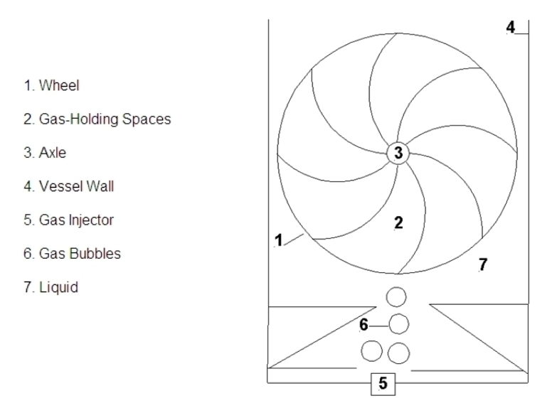
The idea is to inject air into the bottom of the water tank, which rises into the wheel's chambers, and causes the wheel to rotate until the air is released near the top. Of course energy is to be extracted from the turning of the wheel.
This was not proposed as an over-unity device, only as a method for extracting energy (that would otherwise be wasted) of pressurized exhaust gases from manufacturing processes. Fair enough, and a worthy goal. But this turns out to be a very inefficient way to do it.
One obvious problem is those air chambers. The inventor seems to realize that the air should be temporarily trapped within some of them. But now let's redraw the picture to show the water and see how this works.
This doesn't look so promising now, does it. Still, some air is trapped, and might force the wheel to turn, just as a compressed air pump in an aquarium turns an immersed waterwheel. But how much energy can we expect to get from the turning wheel?
That's an easy one. At most, assuming an idealized case of zero friction and viscosity, we'd get out no more than the energy required to inject the air into the bottom of the tank, against the pressure of the water. With a real wheel in viscous water, peformance would be much worse. If you want to drive a motor by compressed air, you can. There are devices (small turbines) that do this rather well. But to do it by immersing a system in water is just silly.
The guy who has this on his website claims to be a consulting engineer. I wouldn't hire him. You can see why I haven't given his name, or the URL of his website. I'm doing him a favor.
Yet another optimistic inventor sends me an underwater belt device using the same flawed principle. He helpfully includes calculations that if his underwater conveyor belt were in 700 feet depth of water (a comparison to Hoover Dam) he'd get 800 horsepower out, for a paltry 30 horsepower used by the air compressor to inject air at the bottom. With a power efficiency of 800/30 = 26.67 I wouldn't care to be near this thing if it did work as he claims. He injects the air into collapsible containers (air bags?), and says they must be streamlined to reduce drag. But he doesn't account for the fact that it takes energy to fill each bag with air, since as it is filled, it displaces water under great pressure (over 21 atm at a depth of 700 ft). He asks me to check his calculations. I charge a consultant fee for such services (to be paid in advance). He can add, multiply and divide correctly, but he badly misuses physics, and frequently considers torque, work and power as equivalent things.
He fails to properly account for two facts:
- The work required to inject air into the bottom of a water column, working against the water pressure there.
- The work expended as the rising air containers expand in size. dW = PdV.
Return to top.
Return to Buoyant Bellows Engines.
Return to the Museum's main gallery.
Return to Donald Simanek's front page.