Constrained overbalance.
The overbalanced cross.
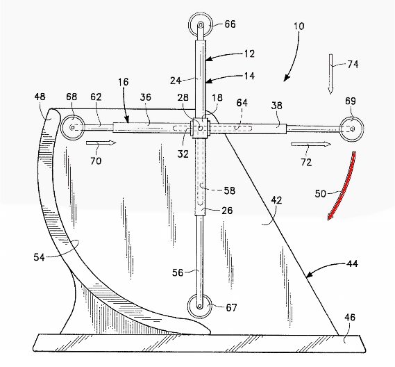
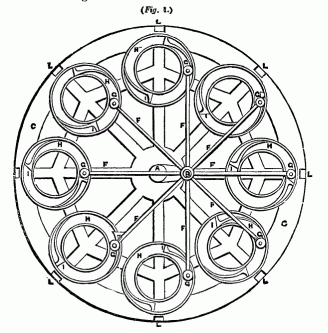
One class of perpetual motion machine gets scant attention in books and on websites. It is a wheel that is kept in continual weight overbalance by an external constraint that forces moving weights so that there's more weight continually on one side of the axle, The unbalance is maintained in in any position of the wheel. Pictures of such devices are seductive. Can anyone doubt that these are in continual overbalance?
 |
 |
| Fig 1. The overbalanced cross. From a patent. |
Fig. 2. Eccentric overbalance |
|---|
Of course Stevin's principle tells us these are non-starters. At one revolution the system is exactly in its initial configuration. Also, since each moving weight moves in a closed path, the net work on each weight is zero during each cycle of the wheel.
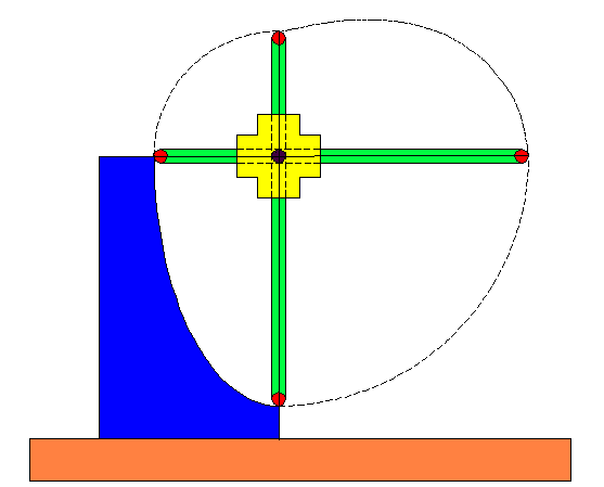 |
| Fig 3. The overbalanced cross. |
|---|
Let's look at the device of Fig. 1. Two crossarms are slotted at the axle so they can slide as the curved ramp (blue) pushes them through the axle. We assume they slide with negligible friction. We have also provided frictionless rollers at the ends of the crossarms (red). The inventor supposes that weight and torque overbalance causes the cross to rotate continually clockwise. For convence we will refer to each crossarm as a "rod" since some versions of this device picture it with rods passing through a cylindrical drum at the axle.
In the position shown the horizontal rod's center of mass is to the right of the axle. The vertical rod's center of mass is directly below the axle. The inventor assumes that since there's a clockwise gravitational torque on the horixontal arm, and none on the vertical arm, then the system must rotate clockwise. If it does so, the rod sliding up the ramp is pushed through the axle, shifting that rod's center of mass above and to the right of the axle, increasing the gravitational torque on that arm. But the inventor forgets that these two rods are rigidly constrained to always make an angle of 90°. We must also not forget that it is the center of mass of the system, including both arms, that determines whether and how the wheel will rotate. That center of mass is at the midpoint of the line joining the centers of mass of the two sliding arms (because both arms have the same mass).
The overbalanced cross analyzed
The overbalanced cross is a nice example of what I call the "overbalance illusion". These are devices that, on superficial analysis, seem to be obviously weight or torque overbalanced, continually. But on careful examination, they are not overbalanced. In fact, most perpetual motion designs that the inventor supposed were overbalanced actually aren't.As the word is used in perpetual motion circles, "overbalanced" means that the system has more mass continually on one side of a wheel's axle, in any position of the wheel. This, if true, would also mean that the sum of the torques torques around the axle would be unbalanced, predominantly in one direction, also in any position of the wheel.
The overbalanced cross is simple in appearance, but cleverly designed to lead us to false conclusions. The sliding arms or rods are an element not often seen in simple machines, and so we have no direct experience with such a system to draw upon.
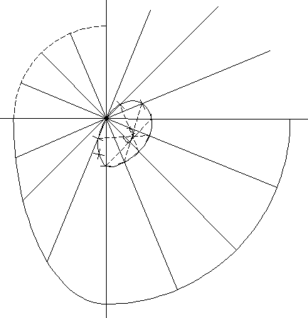 |
| Fig. 4. Analysis of the overbalanced cross. |
|---|
One tricky thing about this device is that it is cyclic, but it repeats its configuration after each quarater turn. This may not have been immediately obvious, and may take a bit of thought to convince yourself of this. It saves us work, for we need only analyze it for one quarter turn.
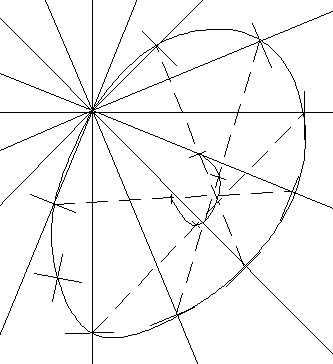
Let's look at the centers of mass of the system parts, and then find the center of mass of the system, that is of all of them together. If the center of mass of the system never rises above the axle, this device is certainlhy not perpetual motion. An accurate diagram will help us through this tricky process. I have chosen the cross shown in Fig. 3, with a ramp in the form of a quarter ellipse. Successive positions of the arms are shown in 22.5° increments (looking like the spokes of a wheel).
 |
| Fig 5. The path of the system center of mass. |
|---|
The center of mass of a single sliding rod is at its center. Each spoke of this diagram represents one of the possible positions of one of the rods. The center of each rod is shown in the diagram by a hash mark. If we locate those centers of mass for each position, and then trace the center of mass motion for just one rod as the device is rotated, the center of mass of one rod traces an orbit shaped like a jelly bean, shown in the graph. But our device has two linked rods, always at right angles to one another. If we now locate the points on this small orbit corresponding to each of these, and join them with a straight line, we find the location of the center of mass of the system. The combined center of mass of the two rods is at the midpoint of this line, since the rods have the same mass. Surprise! The system center of mass never rises above the axle. So this device is not continually overbalanced. It is not overbalanced in any position. Most people find this result surprising, for they thought that the ramp pushing the rods to the other side of the axle would overbalance the system.
A continuously overbalanced wheel is unbalanced in any position, so it will start itself from any starting position. It would always start in a particular direction, never in reverse. A system that won't start itself from any position isn't continuously overbalanced in any position.
Where is this device in static equilibrium?
A correspondent wondered whether this device has an equilibrium position, and where that might be. In general this is a difficult calculation. But our CAD diagram of Fig 7 can provide the answer, at least approximately. Fig 8 shows the small curve traced out by the center of mass as the system moves through 90°. It has a lowest point, a point of equilibrium, at when the arms are in the position shown in Fig. 3. This suggests that if this device is given a slight push in either direction, it will move as a pendulum, and with friction, settle to the position with the arms vertical and horizontal. This means that the system center of mass will rise from its equilibrium position if the cross is pushed in either direction. It will not come to rest with one arm partway up the ramp.
What about torques?
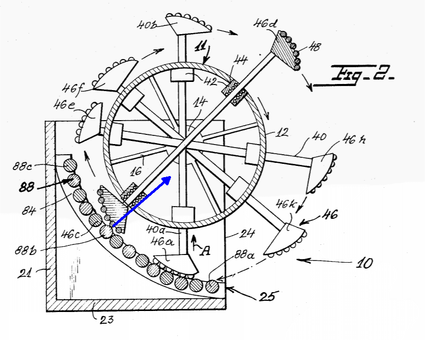
The inventor has neglected a force and its torque—a common blunder. The rod in contact with the ramp experiences a force from the ramp. It must, no matter what shape the curved ramp, exert a force normal (perpendicular to) the ramp surface at the point of contact. In the ramp shown, that force will be a vector aimed below the axle, and therefore its torque will be counter-clockwise. You may hope you could "fix" that by redesigning the ramp to a different shape. But any shape you choose that goes from radius R to a smaller radius r will make that force aim below the axle. Geometry has "gotcha" again.But what does this torque do? It exactly counters the gravitational torque due to the system center of mass being to the right of the axle—when one rod arm is in contact with the ramp. But in this double armed device, one rod arm is always in contact with the ramp.
How about using more sliding rods?
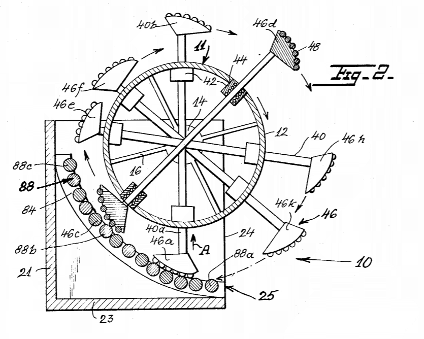
If you make this device with more arms, it still won't work. We illustrate this with another example from the patent literature, Patent US3625089 granted to Edweard Rutkove in 1970.
 |
 |
| Fig 6. Patent US3625089. Edward Rutkove. | Fig 7. The neglected force. |
|---|
Rutkove has added ball bearings everywhere, in an attempt to minimize friction. But ignore those. Even if friction were zero this device isn't perpetual motion. He has a simple circular arc ramp. The force he's neglected is shown (blue) in Fig. 7, normal to the curve of the ramp, and directed below the axle for all positions on the ramp. It provides a counter torque on the cross.
Contact forces and torques do no work unless the body producing them moves. This ramp is massive and stationary, so it does no work on the rods. An everyday example of this is seen when a very elastic ball bounces from a concrete floor. The floor barely moves and does negligible work on the ball. So the ball's kinetic energy remains nearly the same just after impact as it had just before impact. The direction of its velocity has changed, however. Remember that velocity is a vector quantity.Rutkove's patent also included an electric drive motor for the wheel! Perhaps this was to overcome friction. He may have assumed that the wheel would "multiply" the work done by the motor. Or maybe he just wanted to deceive the patent examiners by avoiding any claims of perpetual motion or over-unity performance of the wheel alone.Another example is a marble rolling in a shallow bowl. Neglect friction for now. Give the ball a push when it is in the bottom of the bowl, it can move up the slope of the bowl, and back down again. At all times its total energy, the sum of its kinetic and gravitational potential energies, is constant. No work is done on it by the slope of the bowl.
But will additional rods, at various angles, help? Suppose we have four rods, every 45°. Two will be at 90°. The other two will also. Since each pair will not produce overbalance, two pairs won't either. This is obviously true for any even number of arms.
Our persistent inventor suggests using an odd number of rods, say three rods at 60° to each other. Now two rods will at all times be touching (and being pushed by) the ramp. We leave this as an exercise for the reader.
Change the shape of the ramp.
 |
| Fig. 9. A straight ramp. |
|---|
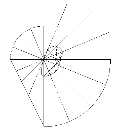
What is the best ramp shape? We chose a conservative quarter-ellipse that smoothly joins with the two circular arcs. It changes slope monotonically and at its endpoints has no slope discontinuity with two concentric circles of different radii. Could a different shape work? Let's choose a radical shape—a straight line.
Fig 9 shows the calculation of, and path of the center of mass of a single rod. Using the same method as before, we trace the system center of mass (both rods), and find it is another small oval near the axle. This is shown enlarged in Fig. 10. Its lowest point is where one rod touches at the bottom of the ramp and the other rod touches at the top. This is the equilibrium position, and the system won't move unless given a push in either direction.
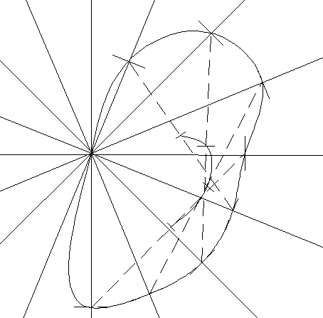 |
| Fig. 10. Enlarged path of center of mass with a straight ramp. |
|---|
Would this system oscillate as a pendulum if given an initial displacement from equilibrium? Here something interesting happens. If a rod, rotating clockwise, impacts the ramp it suddenly experiences a sudden force of impact, normal to the ramp. (In our previous curved ramp example, we avoided this by choosing a curve that presented minimal discontonuity of the slope angle at its ends.) If we assume rigid materials, nearly elastic, this impact can cause the rod to bounce, losing contact with the ramp. Nonetheless, in this idealized frictionless case, periodic swinging motion with impacts will continue. The impacts will not decrease the energy of the system, as we noted above in the example of the ball bouncing from a rigid floor. One could geet picky and note that for perfectly elastic and frictionless surfaces, bouncing from an immovable surface would result in an infinite force for an infinitessimal time. That's just one of those pesky things that happens when you idealize things beyond the limits of reality. Unfortunately, in the real world, inelastic bodies and frictionless surfaces always dissipate energy and make performance worse than ideal.
And there's another problem with the straight ramp. At some point on the ramp the normal force on a rod at its point of contact will pass through the axle. Its torque will be zero. At this point, if moving clockwise, the rod will lose contact with the ramp. So, in fact, there will never be a clockwise torque on a single rod. And, surprise, this will be true for any smoothly curved ramp.
Where is this point? It is when the perpendicular to the ramp passes through the rotation axis. Then the ramp's force on the rod has zero lever arm and zero torque. Nothing opposes the clockwise gravitational torque on a rod. Note that this is not the same point where the rod's center of mass is highest.
Build it!
When a perpetual motion machine inventor sends me long emails defending his idea, I generally say, "Enough talk. Build a working model and then tell me how it performs." Of course, in these cases, "working" models turn out to be unworking models.But much can be learned from building and manipulating such a model, and there are many examples on the web. Here's a nice model of a faked overbalanced cross. Of course this one is faked, only intended to show how PMM inventors suppose it should work. Notice the smooth rotation, indicating a hidden energy source, perhaps a motor, driving it. If this were unfaked, its motion would not be so smooth.
Here's one that has no fakery, an honest overbalanced cross . Notice that it has N positions of equilibrium if it has N arms. It has liberal use of dry ball bearings, and all parts move smoothly. The only way to keep it turning is to crank it.
Return to the top of this document.
Return to the Museum's main gallery.
Return to Donald Simanek's front page.