Siphon Misconceptions.
Misinformation about siphons.
Textbooks and web sites sometimes have statements about siphons that are incomplete or misleading.
- Some assert or imply that air pressure drives the liquid flow.
- Some suggest or imply that it is the difference in weight of liquid in the two siphon arms that causes and sustains siphon action.
- Some suggest that water is lifted (pulled) up the input tube by some mysterious force.
- A website asserts that a siphon could not work on the moon (or in a vacuum), because the outside pressure is zero.
The Meriam Webster dictionary (Encyclopedia Britannica Corp.) defines a siphon: "A tube bent to form two legs of unequal length by which a liquid can be transferred to a lower level over an intermediate elevation by the pressure of the atmosphere in forcing the liquid up the shorter branch of the tube immersed in it while the excess of weight of the liquid in the longer branch when once filled causes a continuous flow."
The Free Online Dictionary defines siphon: "A pipe or tube fashioned or deployed in an inverted U shape and filled until atmospheric pressure is sufficient to force a liquid from a reservoir in one end of the tube over a barrier higher than the reservoir and out the other end."
The Wikionary gets it mostly right: "A bent pipe or tube with one end lower than the other, in which hydrostatic pressure exerted due to the force of gravity moves liquid from one reservoir to another."
I've often thought that "Explain how a siphon works" would be a good question for Ph.D. physics oral exams. I'll bet most candidates would get it wrong.
It's also interesting to note how many modern textbooks avoid any mention of siphons.
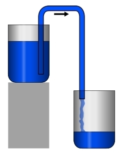 |
| Fig. 1. The Siphon. From The Wikipedia. |
|---|
What is a siphon?
First, let's define "siphon".The siphon is a liquid reservoir with an inverted U-tube. The liquid initially fills the tube. (There are several methods to achieve this initial state.) The purpose of the siphon is to drain liquid from the reservoir by liquid flow that passes over a higher level than the liquid surface in the reservoir. The net result is that the liquid passes from the reservoir to a lower level and does so continually and without external energy input until the reservoir level falls below the ouput end of the U-tube. The practical difference between a siphon and a leaky bucket is the fact that the liquid passes to a higher level before draining out to a lower level.
So we have several things to explain. (1) Why does the liquid continue to fill the siphon tube completely, even though that requires water to rise to a higher level than the liquid level in the reservoir? and (2) Why does the liquid sustain its motion through the tube?
Water rising in the input tube. The liquid barometer is an example of water rising above the level of a reservoir. A tube closed at one end is filled with the liquid, then the closed end is raised up while the lower end is immersed in the liquid reservoir. The liquid in the tube stays there, until the tube height is greater than a certain height that depends on the density of the liquid and the pressure of the air outside the tube. Then a near-vacuum forms above the water in the tube, and the water level does not rise further.
Air pressure is sufficient to sustain a liquid height of about 34 feet for water, only about 32 inches for liquid mercury. Above that height, a near-vacuum forms above the liquid in the closed tube. Actually, the pressure there is the vapor pressure of the liquid. At 20°C the vapor pressure of water is 2.3 pascal, or 17.5 mm Hg. (The vapor pressure of mercury is 0.2729 mm Hg.)
This tells us that if the height of the U-tube of a siphon were too great, the same thing would happen, and a near-vacuum would be created near the top of the U-tube. This would interrupt the continuity of liquid in the tube, and siphon action would stop. This is exactly what happens. Ancient Roman engineers who built siphons into their water aqueducts were quite aware of this limitation of siphons.
In this case we must be clear about the reason that the siphon would fail if the U-tube were too high. It is simply because air pressure on the input side is insufficient to raise the input liquid column as high as the top of the tube. If it doesn't get to the top, it won't flow over to fall down the output tube. So air pressure is important to siphons by putting a limitation on how high they can lift water, and without lifting the water to the top of the U-tube, no siphon flow can occur.
What sustains the liquid flow?
But this isn't the whole story. Is it air pressure that sustains the water flow in a siphon? It is not.If siphon flow is analyzed, with a (nearly) incompressible liquid like water, the work done at each end of the siphon against air pressure is NET zero, for equal volumes of air are displaced at each end. The two ends (water surface in bucket and at the output end of the tube) are both at the same atmospheric pressure, p, so pdV is the same size for equal volumes displaced, but the signs are opposite. So air pressure does not drive the siphon.
Siphoning in a vacuum. If there were no air pressure, could a siphon work? Yes, at least for some liquids, but something else would be required to cause the liquid to form a continuous path through the elevated U-tube. Very cohesive liquids can do this, the molecules attracting each other so strongly that they can maintain a chain-like continuity up and across a U-tube, yet still maintain liquid properties. This has been demonstrated in the laboratory. See: Siphon in a vacuum.
So continuity of the liquid in the U-tube is essential for a siphon. The continuity can be sustained by external air pressure, but even in the absence of surrounding air, cohesive forces in some liquids are sufficient to pass over a modest height of the U-tube. So we can conclude that air pressure is not always necessary to provide the conditions necessary for a siphon. But air pressure is never the reason that the liquid maintains flow through the siphon tube, for any kind of liquid.
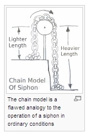 |
| Fig. 2. The naive chain analogy. From The Wikipedia. |
|---|
Maintaining the flow. Let's suppose we have the conditions necessary for a siphon, with liquid from the reservoir filling the tube. The output portion of the U-tube is necessarily longer than the length of the input portion (measured from liquid level to top of U-tube). So it is all too tempting to think of this as something like a pulley and rope with unequal weights attached to the rope on either side. Then the heavier weight "pulls down" the other one. This misconception is reinforced by thinking of the liquid in the tube by analogy with a smooth and flexible chain passing over a pulley. But that's the danger of naive analogies, they ultimately break down, for the two situations are never completely alike.
A failed siphon model. A few years ago a journal article stimulated some controversy in journals and on the web. Hughes, Stephen W. (2010) A practical example of a siphon at work. Physics Education, 45(2), pp. 162-166. Hughes exposed a serious error in dictionary definitions of "siphon", especiaially The Oxford English Dictionary definition: "A pipe or tube of glass, metal, or other material, bent so that one leg is longer than the other, and used for drawing off liquids by means of atmospheric pressure, which forces the liquid up the shorter leg and over the bend in the pipe." This definition is misleading in several ways. But Hughes went on to propose cohesion and the "chain model" as the reason for siphon flow, ignoring the role of liquid pressure gradients.
This chain model was refuted. See: Siphons, Revisited. Alex Richert and P.-M. Binder, University of Hawaii at Hilo. The Physics Teacher, Vol. 49, February 2011.
 | |
| Fig. 3. Reverse siphon? From The Wikipedia. |
Fig. 4. Vittorio Zonca's 1607 mill. From Dircks (1861). |
|---|
The chain model treats the siphon flow as due to different weights of liquid in the two siphon arms. If it were the weight in the arms of the U-tube that causes and sustains liquid flow, then this hypothetical reverse siphon (Fig. 3) ought to work, causing flow from right to left since the left side of the tube contains more liquid and clearly must be heavier. In fact this ought to allow a siphon to raise liquid from lower to higher levels. Vittorio Zonca (1568-1602), In his folio Novo Teatro di Machine et Edificii (Padua, 1607) even proposed this idea as if it could be a useful device to lift water to drive the waterwheel (or turbine) of a mill. (Fig. 4.) Of course it could never work. In fact, this overbalanced siphon flows from left to right, from higher to lower level, just as an ordinary siphon does.
The self-flowing flask of Robert Boyle.
This is a digression, which the reader may skip.Robert Boyle (1627–1691), discussed the "hydrostatic" paradox to reveal the misconception involved. His clever example was a "self-flowing" flask (Fig. 5). Why doesn't the greater weight of liquid in the flask force liquid to a higher level in the narrow tube so that it spills over and flows back into the flask. Perpetual motion! Add a small waterwheel just below the outlet and you could extract energy from the fluid flow. If there were any flow.
 |
| Fig. 5. Boyle's "self-flowing flask". The Hydrostatic Paradox. |
|---|
Even today there are people who see this picture of the flask and can't imagine why it doesn't work. College students are often puzzled by it and at a loss to explain its fallacy. Zonca can be forgiven, for he lived at a time before the concept of force was well understood, and long before vector analysis of forces became a standard tool for analyzing physical systems. Today's physics students have no such excuse.
To make the story short, the misconception here is to suppose that the entire weight of the liquid in the flask must be supported by the smaller weight of liquid in the tube. This seems impossible, so one imagines the liquid must flow from left to right.
But the weight of liquid is partly supported by the sloping walls of the flask. The wall exerts forces normal (perpendicular) to the wall, and these have upward components. The liquid in the flask is not entirely supported by weight of liquid on the right, but largely by the flask walls. Overlooking that fact leads to the apparent paradox.
The Flemish scientist Simon Stevin (1548–1620) first explained this. The French mathematician Blaise Pascal (1623-1662) illustrated it with a demonstration device, Pascal's Vases, which had glass flasks of various shapes and orientations connected to a common water reservoir. The water level in each flask, whatever the flask's shape, was at the same height. Of course this is the essence of Aristotle's principle that "Water seeks its own level."
 |
| Fig. 6. Pascal's vases (left). The pressures at A and B are the same. Showing forces due to the vessel walls (right). |
|---|
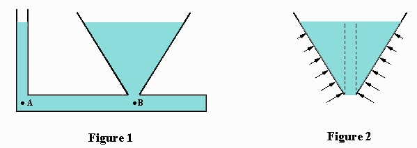
Fluid pressure differences maintain the siphon flow. We have seen that it isn't the weight difference in the U-tube arms that initiates flow. It is the pressure difference within the liquid that does that. It helps to realize a fundamental fact about hydrostatics. The pressure difference between two points in a liquid is equal to ρgH where ρ is the liquid density, g is the acceleration due to gravity and H is the height difference. This is true so long as the liquid has continuity between the two points, that is, if a continuous line can be drawn between the points, passing only through the liquid.
 |
| Fig. 7. A continuous line may be drawn through the liquid, connecting points A and B. Therefore the pressure difference between these points is ρgH, where ρ is the liquid density. |
|---|
The reader may object that the siphon's liquid flow isn't a static situation, but a dynamic (moving) one. True. But when a siphon is constructed, one initially fills the tube and closes off the lower end of the tube, preventing fluid flow. This is a static situation and a pressure difference between the lower end of the tube and the liquid level in the reservoir is established. The pressure inside the closed end is higher than atmospheric pressure. (In fact it is higher than anywhere else in the system.) As soon as the lower end is opened, the pressure there drops to atmospheric pressure and a lower pressure pulse travels up the tube at the speed of sound in the liquid. When the pulse reaches the top, lowering the pressure there to less than atmospheric pressure, the liquid in the input tube rises as flow is initiated. Very quickly a new pressure gradient is established in the tube, allowing continuous flow. To analyze this, the obsessive reader may wish to apply Bernoulli's equation to recalculate the altered pressures. Or consult this paper The Siphon, by A. Potter and F. H. Barnes, Physics Education, 42, 488 (1971), to see how it is done.
The bottom line.
It isn't atmospheric pressure that sustains the siphon flow. The weight difference of liquid in the tube arms isn't the reason for siphon flow. The siphon's flow is a result of the gravitational potential difference between the liquid level in the reservoir and at of the output tube's opening. Gravity is necessary for siphon operation. The siphon is an unbalanced system with stored gravitational potential energy that sustains the liquid flow.(A critical reader has correctly observed that cohesion between particles is essential for siphons. He says "you can't siphon sand".)
- —Donald E. Simanek
© 2014 by Donald E. Simanek. Latest revisions Oct. 2013, Jan 2014.
Send comments, corrections and additional ideas to the address shown at the right.
Return to top.
Return to the Museum's main gallery.
Return to Donald Simanek's front page.