The sliding slot puzzle.
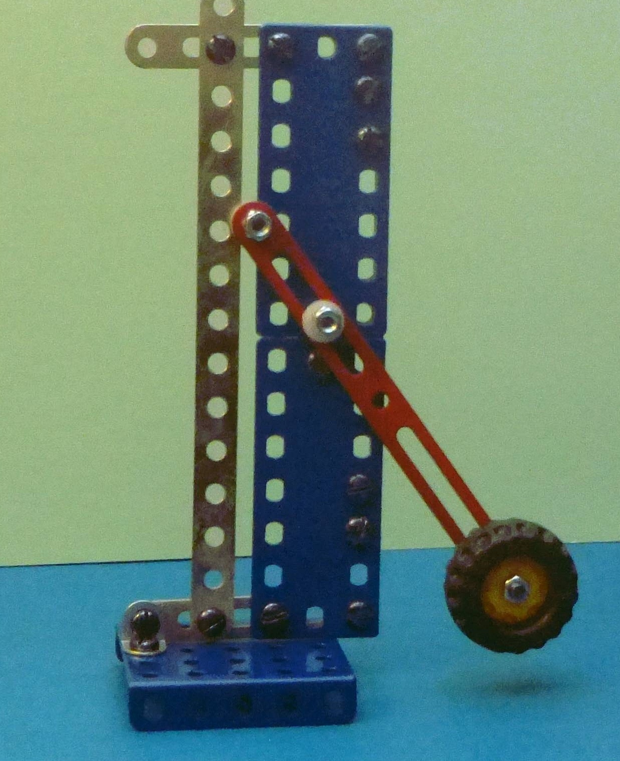 |
| Fig. 1. The sliding slot mechanism. |
|---|
Here's a simple device, using a slotted beam. The red beam has a smooth slot sliding on a fixed frictionless axle. The left end has a pin that slides up and down in a vertical rigid frictionless slot. A yellow and black weight is at the right end of the beam.
Fig. 1 shows a small model of this device made with a metric steel construction set. The holes are spaced 1 cm apart. Fig 2. shows the geometry of the model. The sliding beam BC is shown in red. The axle is at A. The vertical slot is a distance H from the axle. The beam AC has length L. The weight on the end of the beam is W.
The system has a position of stable equilibrium, and a position of unstable equilibrium. Find them. We seek an answer giving the angle of equilibrium in terms of H, W, and L.
 |
| Fig. 2. The geometry of the sliding slot. |
|---|
Comments: We have assumed frictionless motion for simplicity. Note that as the beam angle changes, the beam slides on the axle A. Assume the sliding beam has negligible weight compared to W. (Or you can assume that the center of mass of a longer beam is at point C,)
There are several approaches to this problem. One is to build a model and see where the equilibrium positions are. Fig. 1. shows the position of stable equilibrium. I call this model a "tap-toy", for tapping it repeatedly joggles the beam until it comes to rest in its stable equilibrium position. Any slight push from that position causes the beam to return to that position. One can actually (with the help of friction) find the position of unstable equilibrium. There, any jostling of the toy causes the beam to move away from that unstable position.
Another approach is to lay the model on a sheet of paper. Remove the weight W. With a pencil or pen, trace the motion of point C as the beam angle is changed. The point of relative minimum height of this curve is the position of stable equilibrium. The position of relative maximum height is the position of unstable equilibrium. This little exercise can be done with cardboard, a thumb tack for the axle, a sheet of paper and a pen. The slot can be cut in cardboard with a razor blade.
This gives a clue for a solution strategy. If we can find the lowest point on the center of gravity curve, we have our answer. This would be a nice calculus problem—if we had an equation for the center of gravity curve, but that might be quite a mess to derive. One suspects there's a simpler strategy.
We could observe that at the lowest point, the path of the center of mass has a horizontal tangent. So can we find a point where any small change of angle causes motion of point C along that horizontal tangent? This looks promising.
Similar methods should work for the position of unstable equilibrium.
Need we say that the weight W doesn't matter? The principle of superposition proves this nicely. Nor need we say that all valid strategies should arrive at the same result. Simple as this mechanism is, this sort of problem isn't often seen in elementary physics textbooks.
Solution.
 |
| Analysis of the slot mechanism. |
|---|
The key to the solution is the remember that when two bodies slide or roll on each other, the action/reaction forces at the point of contact are perpendicular to the tangent at that point. So the vertical slot exerts a horizontal force on the beam. At the axle, the net force on the beam is perpendicular to a wall of the slot in the beam. This is the fact that students often miss when analyzing this sort of problem.
The net force acting at any point is zero when the system is in equilibrium.
The net torque about any chosen point is zero at equilibrium. Taking the torques about point B, gives W H + N y = W L cos(α) where y is the length AB and L is the length of the beam AC.
The force N is the force at B of the axle on the beam AC. It must be perpendicular to the beam.
We see from vector triangles that y = H tan(α) and, looking at the two components of force acting on the axle, we have tan(α) = N / W. So N = W tan(α).
Substituting and eliminating y, we have W H + W tan(α) H tan(α) = W L cos(α).
This reduces to H [ 1 + tan2(α) ] = L cos(α).
The weight has obligingly dropped out, as we knew it must. The ratio H / L also appears, as we expected.
And, finally, L cos(α) = H [ 1 + tan2(α) ] .
For the dimensions of our model, H = 1.7 cm and L = 7.9 cm. This gives the result α = 53.2°. This result was obtained by iteration, entering values of α until the equation was satisfied. It also agrees with experiment, by jiggling the mechanical model to find the position of stable static equilibrium.
By the same method, we find that α = -53.2 degrees also satisfies the formula. This is the position of unstable static equilibrium, The stable and unstable positions are symmetrically located with respect to the horizontal axis. This is expected, since the mechanism's motion is symmetric about that axis. We will see that again in the alternative solution that follows.
Geometric solution.
 |
| Geometry of the slot mechanism. |
|---|
Though we used a force and torque analysis in the solution above, this isn't necessary. This is fundamentally a problem in Euclidean geometry.
The figures shows the slotted beam in two positions, just slightly displaced by angle φ, though exaggerated here for clarity. The axis, point A is fixed, as is the left vertical and fixed slot, a distance H from A.
As before, the beam length is L = a + b measured from the left end to its center of mass.
We use the physical fact that at stable eqilibrium the center of mass of the beam is at its lowest point. The path of the center of mass as a function of angle α has a relative minimum height there. So at that point the tangent to the CM curve is horizontal. Any slight displacement of the slotted beam moves its right end horizontally, in the limit as the displacement angle φ goes to zero. Our figure represents this, with φ exaggerated for clarity.
As the beam rotates clockwise, its upper end moves up and its lower end moves horizontally. These motions may be decomposed the sum of two motions, simple rotation, and the motion as the beam is pushed across the axle, which we designate p. These combined motions form two right triangles, which we enlarge at the right of the figure.
The skinny triangles with vertex at A have arcs (a φ) and (b φ) and since the angle φ is very small (and we are interested in the limit as φ goes to zero) we treat them as approximately straight.
As in the previous solution, H = a cos(α)
From the triangles tan(α) = p / a (φ) and tan(α) = b (φ) / p
Combining these, p / φ = a tan(α) = b / tan(α), so b = a tan2(α).
L = a + b = a + a tan2(α) = a ( 1 + tan2α) .
Using a = H / cos(α), gives L = [H / cos(α)] [ 1 + tan2α]
This rearranges to L cos(α) = H [ 1 + tan2α] which was our previous result.
 |
| Paths of the center of mass. |
|---|
I have presented this as a non-calculus solution, in the spirit of Eratosthenes and Archimedes. The readers who prefer calculus are welcome to derive the equation of the CG curve and find where its slope is zero by taking its derivative with respect to theta and setting it equal to zero. If you do, let me know the equation you derive for the CG curve. I know what it looks like, for I traced it manually using my little mechanical model.
The tracing shows several curves, for different locations of the beam's center of mass. Our diagrams, and analysis have assumed a weight W on a beam of negligible mass. For the actual model, the center of mass of beam and weight was found by removing the beam and weight and experimentally locating the point where it is in horizontal balance. It was suspended from a string. That point was slightly to the left of the black/yellow weight.
The symmetry of this device about the horizontal axis tells us that the position of unstable equilibrium is at the top of the curve at its relative maximum, and is at an angle above the horizontal equal to the angle of the position of stable equilibrum below the axle.
Return to Physics puzzles.
Return to The Museum of Unworkable Devices.
Return to the Donald Simanek's home page.