D-6 ANGULAR ACCELERATION
1. PURPOSE
To determine the moment of inertia of a rotating body and to calculate the torque due to friction in its bearing.
2. APPARATUS
(a) inertia disk apparatus
(b) bicycle wheel mounted on ceiling
(c) ball bearing pulley
(d) moment of inertia apparatus (disk and ring)
Also: Weights and weight hangers, string, stop watch.
[Note: each of these four alternate experiments will occupy a full laboratory period. Consult the instructor to find out which are available for you to choose.]
3. THEORY
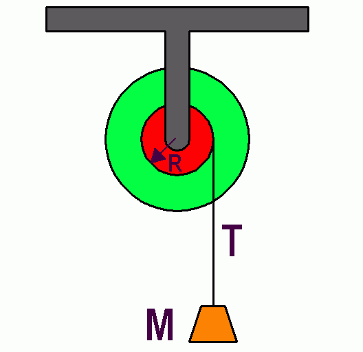 |
| Fig. 1. Wheel with axle. |
|---|
These experiments are studies of a cylindrically symmetric body (a disk or wheel) constrained to rotate about a fixed axis. It is caused to accelerate by an externally applied torque, and the acceleration is measured. The retarding torque at the shaft or bearing may also be measured.
From these data two results may be determined:
(a) The moment of inertia of the body.
(b) The torque due to friction and rolling resistance in its shaft or bearings.
A weight, W, is hung from a string wrapped around the axle shaft, or around the perimeter of the body itself. The tension, T, in this string supplies the accelerating torque.
The accelerating torque is:
[1] Ga = T R
where Ga represents the applied torque and R is the radius of wrap of the string.
While the system is accelerating, there is another torque acting at the shaft or wheel bearing, due to friction and rolling resistance, Gf. This torque opposes the applied torque, so the net torque on the body is (Ga - Gf). The net torque produces an angular acceleration
[2] Ga - Gf = I α1
where α1 is the observed angular acceleration.
Another equation is obtained by considering the forces acting on the hanging weight:
[3] W - T = Mg - T = Ma
where M is the mass of W. The acceleration, a, is the linear acceleration of W and is related to the angular acceleration of the body by
[4] a = α1 R
Equations (1) through (3) may be combined to give:
[5] M(g - a)R - Gf = I α1
(show the missing steps.) This equation still contains two unknowns, I and Gf, so another relation must be obtained experimentally which may then be solved simultaneously with Eq. 5. There are two ways to obtain a second relation. They are described below:
Method 1. Do the experiment again with a different value of W. This will result in a new value of acceleration and a new equation like (5) which may be called (5'). Since the small weight W causes only a small fractional increase in bearing thrust, it may be assumed that Gf is the same in both equations, so (5) and (5') may be solved simultaneously.
Method 2. It is possible to determine the acceleration, a, directly, by observing how long it takes W to fall from rest through a measured distance, using:
[6] 1 2 s = — a t 2
where s is the distance of fall. In this case the final velocity of W may be found from:
[7] v2 = 2as
and the final angular velocity of the rotating body may be calculated from:
[8] ω = v/R
This acceleration is terminated by the removal of the applied torque. The rotating body will then decelerate and eventually come to a stop. This time it takes to do this, t2, is measured, and the angular deceleration is then:
[9] α2 = ω/t2
The relation between Gf and I may be written:
[10] Gf = I α22
Equations (5) and (10) may now be solved simultaneously to obtain values for I and Gf.
4. PROCEDURE
Several different experiments are available to illustrate the theory. These are described separately below.
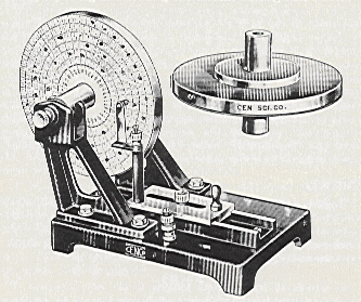 |
| Fig. 2. The Inertia Disk. [CENCO] |
|---|
This apparatus consists of a massive steel disk on roller bearings. The disk is of simple shape and it may be removed from its bearings so that its dimensions and weight are easily found. Its moment of inertia may be calculated from the standard formula for a cylinder, since the wheel is made up of several cylindrical shapes. This direct calculation is made solely as a comparison check for the value of moment of inertia be obtained by a dynamical method.
Do not ignore the moment of inertia of the axle.
The acceleration α1 is determined from a spark timer record made directly on a waxed paper disk taped to the side face of the rotating disk. This record may be made in either of two ways.
(a) A spark timer, operating at 120 Hz is connected so that a spark jumps from a metal point through the waxed paper to the disk.
(2) A pointed stylus, vibrating at 120 Hz, lightly touches the waxed paper, leaving a wavy line on the waxed surface.
Whichever recording device is used, it may be moved by hand radially on the disk as it rotates, so that the records of successive revolutions do not overlap. It is best to move it from the outside toward the inside of the disk. Why?
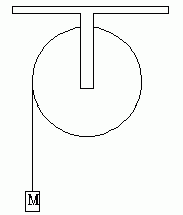 |
| Fig. 3. The bicycle wheel. |
|---|
The data analysis is easiest if the angular position of every 12th spark (or every 12th period) is measured. This gives time intervals of 0.1 second. The method of differences may then be applied to this data.
Either method 1 or 2 may be used to obtain a second equation. Method 1 probably gives more accurate results, but use both and compare them.
A bicycle wheel with heavy tire is located near the ceiling, its axle horizontal and rigidly fastened to the ceiling. The torque is applied at its circumference by a string looped over a thumb tack taped to the tire. No elaborate timing methods are used here; the acceleration is small enough to time with a stop watch. Method 2 is used. This may be set up as an Atwood machine and analyzed as described in D-6c.
 |
| Fig. 4. The Atwood Machine. |
|---|
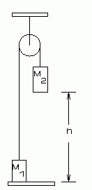
A ball bearing pulley is used. The friction is small, but it can be measured if data is taken with care and an appropriate data analysis method is used. The mass of the pulley is also relatively small, so care must be taken that the torque due to friction is kept constant as the other variables are changed. This may be done by keeping the total weight, W1 + W2 constant during two trials and using method 1 for analysis.
Since two weights are now involved, the equations must be reworked from the beginning, noting that the string tensions on the left and right sides of the pulley are not equal. Therefore two tensions, T1 and T2 will appear in the equations.
With reference to Fig. 2, derive the equation for this system. The equation can be cast in a form similar to that of equation (5).
The result is:
[11] [(W2 - W1) - (W2 - W1)(a/g)] R - Gf = I α1
Or, in better form:
[12] (W2 - W1)(1 - g/a) R - Gf = I α1
The first term is more complicated than the corresponding quantity of equation (5), but it may be simplified by inserting the numerical values of the weights, and g, before doing further algebra.
Some ingenuity will be required here. Examine the error propagation equations to determine what relative size of quantities will give the least error in the results. A long distance of fall may be desirable.
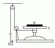
This commercial apparatus is especially designed to measure the moments of inertia of simple objects, such as a flat disk and a ring. The basic apparatus consists of a simple support table which rotates about a vertical axis. The object to be studied (disk or ring) fits onto this support and rotates with it about the same vertical axis.
 |
| Fig. 5. The Moment of Inertia Apparatus. |
|---|
The specimen is accelerated by a torque applied by a string wrapped around the axle of the support table. The other end of the string goes over two pulleys and is attached to a weight hanger, arranged to give as long a fall as possible.
The mechanics of the system are as described in the theory. There is no spark timer; stop-watch timing must be used. Arrange the experiments so that the measured times are long enough to contribute negligible error.
Spend quite a bit of time in "experiment planning" and calculation of experimental uncertainties. Note that here the specimen masses are large compared to the support table mass. Therefore you cannot assume that the frictional torque in the bearing is the same in each case.
Be aware of such things as (a) the effect of starting friction on measurements when the table starts from rest, and (b) the contribution of pulley friction.
The experiment should give good numerical values for (a) the moment of inertia of the rotating part of the supporting table assembly, (b) frictional torque in the bearing as a function of load, (c) moment of inertia of the disk, (d) moment of inertia of the ring. Check the results by comparing (c) and (c) with the direct calculation made from mass and geometry measurements.
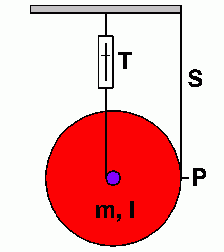
The apparatus is simple. It consists of 2 foot diameter masonite disk with a 1/4 inch dowel axle. It is a giant Yo-Yo toy.
|
A large, uniform disk (red) has a small axle (blue). It is suspended as shown, with a spring balance at T, and another string S, loosely attached to a peg P at the rim of the disk. The disk mass is m, and its moment of inertia is I. The radius of the red disk is R and the radius of the small blue axle is r.
(1) What is the reading of the spring scale in the situation shown?
(2) The string S is cut, or burned with a flame so that it falls freely and now the only support of the disk is the tension in the other string, T. What is T at the moment after string S is cut?
(3) The disk begins to fall and rotate. What is its linear acceleration and its angular acceleration? What is the spring scale reading now? It is NOT T. Is it larger or smaller than T? s this scale reading constant with time? If not how does it change over time?
Now do the experiment and check your predictions.
This is the only part of this experiment where you must deal with a body that has both linear and angular momentum. When the disk reaches its lowest point, its linear momentum abruptly changes direction. Discuss how this can happen. What is the disk's linear momenum value at the lowest point? Have you ever puzzled over these things when playing with a toy yo-yo?
5. QUESTIONS
(1) Answer all questions and do any derivations suggested in the experiment you performed.
(2) Show that Eq. 11 reduces to Eq. 5 when either of the weights is made zero.
(3) Discuss how you might obtain the moment of inertia and bearing friction of a bicycle wheel with the following method. Measure the time for an accelerating weight to fall a known distance, as in method 1. Now attach known weights at known, equal radii to the rim of the wheel. Now measure the time for the same accelerating weight to fall the same distance as before. This time will be longer, due to the increased moment of inertia of the wheel. Derive the necessary equations and show how the calculation could be carried out.
(4) Discuss how you might obtain the moment of inertia and bearing friction of a bicycle wheel with the following method. Measure the time for an accelerating weight W to fall a known distance, as in method 1. Now use the wheel as an Atwood machine, using two weights which total the weight used before, W. Discuss and analyze, as in question (3)
(5) In part D-6e is the spring balance "weighing" the falling disk? If so, why does it weigh less than when the disk is falling? If not, why not? How does this square with the definition of weight?
Text and line drawings © 1998, 2004, 2014 by Donald E. Simanek.
