K-2 THE ATWOOD MACHINE
(1) To study the acceleration of an Atwood Machine arrangement of masses and pulley.
(2) To investigate the effects of the pulley moment of inertia and friction.
(3) To determine the moment of inertia of the pulley by two methods.
(4) To determine the bearing friction in the pulley and to find out whether it depends on system mass loading.
2. APPARATUS:
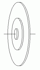
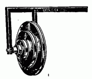
Cenco 75746 Aluminum Wheel and axle (a pulley with several different
radii),
light string,
two weight hangers,
slotted weight set,
meter stick,
stop watch or other timer.
Any pulley may be used, including ball bearing pulleys.
3. PROCEDURE:

The "wheel and axle" is a commercially available piece of apparatus designed for a very different experiment (mechanical advantage). It has several advantages for this experiment:
(1) Several different radii are available for use in the Atwood Machine arrangement.

(2) The pulley may easily be removed from its cone bearings for weighing. Once removed, it may be suspended and swung as a physical pendulum, in order to independently determine its moment of inertia.
[A knife edge suspension will be used, just under the outer part of the pulley, and the period determined for small oscillations of the pulley.]
Devise an experimental procedure to achieve the experimental objectives. Seek a graphical method of analysis. The error propagation analysis may be messy, so work out the error equation for several methods before choosing a strategy and taking data. With this apparatus you should be able to obtain the pulley moment of inertia to better than 10%. The determination of the bearing friction may not be that good.
HINTS:
|
|
- Avoid the temptation to use large weight imbalance, for that results in high speeds that are more difficult to time accurately with a stop watch, and very likely will result in the weight holders crashing to the floor and spilling the weights.
- The pulley has moment of inertia as well as resistance, which may arise from several sources. These are lumped together as I and τ. A suggested method is suggested in the "method" sections below, using the "equivalent mass" of the moment of interia.
- There could be great advantage to keep the pulley conditions constant for all trials. Thus the total loading of the pulley can be kept constant by keeping the total weight on the hangers constant, transfering weights from one side to the other.
- One practical method of timing requires a clever modification of the equipment. Digital stop watches and electric timers may be easily opened to allow soldering of two wires to the "start" button. These then are connected to two metal pulleys, one insulated. Instead of string, use a very light, strong, and flexible wire for the suspended weights, passing over he metal pulleys. This wire will complete the timing circuit to operate the stopwatch. The wire has string at each end so that the wire makes contact with the pulleys during only part of the fall, but this is a constant length and easily measured.
This method follows Wilson's laboratory manual.
With masses m1 and m2 as the ascending and descending parts of the system, the net force on the system is:
| [1] |
Fnet = m2g - m1g - (m2 - m1)g
when the pulley friction and moment of inertia are neglected.
By Newton's second law,
| [2] |
Fnet = ma = (m1 + m2)a
where m = m1 + m2 is the total mass of the moving system. Then, equating Eqs. (1) and (w), we have
| [3] |
(m2 - m1)g = (m1 + m2)a
or
| [4] |
The analysis so far has been idealized for clarity. In reality there's frictional force f associated with the pulley, opposing the motion. [f = t/R where t is the frictional torque.] The pulley also has a moment of inertia, which can be represented as an additional "equivalent" mass meq. [meq = I/R2, where I is the pulley moment of inertia and R is its radius.] Hence, for better accuracy, Eqs. 2 and 4 should be modified as follows:(m2 - m1)g a = —————————— m1 + m2
| [5] |
Fnet = F - f = (m2 - m1)g - f = ma = (m1 + m2 + meq)a
or
| [6] |
    (m2 - m1)g - f
a = ——————————————
     m1 + m2 + meq
If the mass system of the Atwood machine moves with a constant velocity, the acceleration a of the system is zero (in Eq. 6) and therefore:
| [7] |
f = (m2 - m1)g = mfg
which provides a method of determining the magnitude of the frictional force of the system. We have used f = mfa, where mf is the effect of friction in mass units. Eq. 6 may then be written
| [8] |
     (m2 - m1)g - mfg   (m2 - m1 - mf) g
a  = ——————————————— = ————————————————
      m1 + m2  + meq       m1 + m2 + meq
Experimentally determine the acceleration of the system by measuring the time t for the descending mass to fall through a given distance y. This acceleration may be compared to that predicted by Eq. 8.
Using the kinematic equation
| [9] |
          1   2
y = v t + — at
     o    2
with the mass starting from rest (vo = 0), we have
| [10] |
    1   2                              2y
y = — at              or           a = ——
    2                                  t2
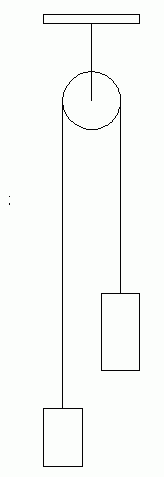
(1) Set up the Atwood machine as shown in Fig. 1. Use enough string so that the descending mass may start near the pulley and descend to the floor. This should be 1.5 to 2 meters of fall. Put weight s on the hangers so that the ascending and descending masses are 200 gm each.
(2) With the masses equal the system is in equilibrium. In the absence of friction a slight vertical force applied with the finger on one mass would set the system in uniform motion (Why?). However, because of the opposing frictional force, the motion will not persist. Add small weights to the descending mass side until a slight tap causes the mass to descend with uniform motion (constant velocity) The weight of the added mass (or the mass difference between the descending and ascending masses) is then equal to the frictional force:
f = mfg = m2 - m1
The frictional force will be considered constant, and mf will be subtracted in the theoretical calculations of the acceleration of the system.
(3) The effects of the acceleration of the system will be investigated separately by varying (a) the unbalanced force and (b) the total mass while keeping the other quantity constant.
Varying the unbalanced force (total mass m1 + m2 = constant.)
1. To maintain a constant total mass while varying the unbalanced force, masses are moved from one side of the pulley to the other. No mass is added to the system after beginning to take data.
2. Place on the order of a total of 200 gm on each side of the system. Include several small masses (5, 2, and 1 gm) on one side that can be transferred to the other side. The procedure will be to transfer mass from one side to the other to obtain four different values of m2 - m1. Make three independent measurements of the time it takes for the descending mass to travel the distance y from rest (Fig. 1) for each case.
The four different values of m2 - m1 should be small so that the acceleration is not too large. Start with the m2 - m1 value that just causes the system to accelerate slowly from equilibrium. Care should be taken when the descending mass strikes the floor. If its velocity is too large, the impact may cause the masses to be jarred from the hanger.
3. Compute the acceleration for each case using the distance and the average time measurements in Eq. 10b. and compute the predicted acceleration from Newton's second law (Eq. 5). Remember to subtract mf in Eq. 5 since the weight of this mass is equivalent to the frictional force of the pulley.
Varying the total mass (unbalanced force kept constant).
1. To maintain a constant unbalanced (net) force, the mass difference m2-m1 is kept constant. The total mass m1 + m2 is varied by adding weights to the system while keeping m2 - m1 constant.
2. Place a total of about 200 gm on each side. Add small weights to one side until the system is set in motion. Make three independent measurements of the time for the descending mass to travel the distance y from rest. Repeat the procedure for three more values of total mass by adding 100 gm to each side for each new value (i.e., keep m2 - m1 constant by adding the same mass to each side of the pulley.)
3. ANALYSIS
Constant mass method. Here you graphed that subset of your data in which the total moving mass remained constant. Plot at versus (m2 - m1). How do you interpret the graph, in particular how do you meaningfully compare it with Eq. 8? Rearrange Eq. 8 in slope intercept form (y = sx + b).
| [8] |
    (m2 - m1 - mf)g
a = ———————————————
 t   m1 + m2 + meq
Rearranged into slope intercept form we have:
| [8b] |
    (m2 - m1) g         mf g
a = ————————————— - —————————————
 t  m1 + m2 + meq    m1 + m2 + meq
Compare this with the equation of a straight line:
y = s x + b
The second term on the right represents the constant b (it has negative sign). The first term on the right represents sx, where s represents the constant g/(m1 + m2 + meq) and x represents (m2 - m1). y represents at, of course. Now, when you make the graph, you'll get a nearly linear relation with slope s and y intercept b. Plot accelerations on the "y" axis, and the mass difference on the "x" axis. Then the slope of the line, s, allows you to calculate meq, since you know all of the other constants. The y intercept (where x = 0; no acceleration) then allows you to calculate mf. (This value should compare well with the amount of mass unbalance which you experimentally found would just initiate acceleration of the system.) These calculations follow directly from the data and this graph. Then you ought to compare these calculated values with those you previously determined experimentally (and crudely). These will agree quite well if you have followed instructions! Question: Why can we assume constant meq here?
Constant unbalanced mass. Here you graphed that subset of your data in which the unbalanced force remained constant (but the total moving mass did not). You graphed the reciprocal of the system's acceleration against the total mass on (and including) the hangers. Therefore, to make a meaningful comparison you must rearrange equation 8 in a different way to get a y = sx + b form.
| [8c] |
1     (m1 + m2)             meq
— = —————————————— + ———————————————
at  (m2 - m1 - mf)g   (m2 - m1 - mf)g
METHOD 2:
The same data may be analyzed in a different manner. This is functionally equivalent to method 1, but this treatment explicitly includes the pulley's friction torque t and the pulley moment of inertia I, and finds the values of both by graphical analysis.
The torque equation is:
| [11] |
(T2 - T1)R - t = Ia
where the T1 and T2 are the tensions in the string on either side of the pulley (not equal), I is the moment of inertia of the pulley, t is the retarding torque due to pulley friction and a is the angular acceleration of the pulley. aR = a applies, where R is the radius of the pulley. Newton's law gives:
| [12] |
m2g - T2 = m2a
and
| [13] |
- T1 - m1g = m1a
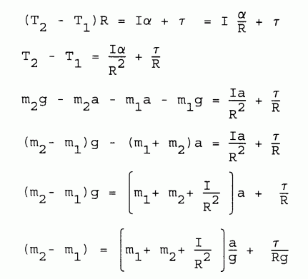
We are assuming that m2 is the heavier mass. Eq. 11-13 must be solved, eliminating T1 and T2 and a. The derivation follows without explanatory comment:
| [14 - 19] |
 |
If (m1+m2) has been held constant, the entire expression [...]/g is constant, and the frictional torque is constant.
This means that one can determine the moment of inertia from the slope of the graph, and the frictional torque from the intercept.
4. QUESTIONS1. In the calculations of this experiment, would a significantly large determinate error result from neglect of the mass of the string? Give a quantitative answer.
2. British scientist George Atwood (1746-1807) used this device to measure the acceleration due to gravity. You have used it for other purposes, treating g as a known quantity. Design an experimental procedure to use the Atwood machine to measure g and tell how that value can be obtained from measurements. What experimental uncertainty could you expect in g from your procedure? Obviously the acceleration due to gravity may be determined from your data. Do this and comment on the method and the result.
3. Rework the equation derivations for the case where there's a significantly large frictional drag acting on the moving masses. (Imagine the Atwood machine being operated underwater.) How would you need to modify the procedure to separate out this friction from the pulley bearing friction, so that the size of each may be determined?
5. When deriving the equations for the Atwood machine we usually combine the equations to eliminate the variables representing string tension in order to obtain an equation for the acceleration. Consider the simplest form of Atwood machine, with no friction and a massless pulley. Write the two free body equations. Eliminate the common acceleration and solve for the tension in the strings. During acceleration, the pulley must supply an upward force equal to the sum of those two tensions. Why isn't this force simply equal to the total weight of the moving masses? Hint: What happens to the center of mass of the system as the system accelerates?
Text and diagrams © 1997, 1998, 2004, 2014 by Donald E. Simanek.