D-7 CENTRIPETAL FORCE
1. PURPOSE:
To verify the equation for centripetal force, specifically confirming the functional dependence of centripetal force on mass, radius, and frequency.
2. APPARATUS:
Sargent-Welch rotation apparatus. Slotted weights. Selection of springs; paper clips. Wrist watch, or stop watch.
3. THEORY:
See any textbook which derives the equation for the acceleration of a body moving at constant speed in a circular path is:
| [1] |
                                v2
Centripetal acceleration,  ac = —— = Rω2 = 4π2Rf2,
                                R
| Definition: The centripetal force is the radial component of the net force on a body. |
|---|
where we use:
v for the speed of the body,
R for the radius of its path,
f for the frequency (revs/sec),
ω = 2πf for the angular frequency (in radians),
Τ ≡ 1/f.
The acceleration vector points radially inward toward the center of the circle. The acceleration vector therefore points perpendicular to the instantaneous velocity of the body at all times. Therefore the acceleration does not change the size of the velocity, it only changes the direction of the velocity.
A body moving in a circular path requires a radial force to produce this radial acceleration. From Newton's law, F = Ma, this radial force, called the centripetal force is:
| [2] |
where M = the mass of the body. Fc is a real force acting on the body, directed toward the center of the circle. The centripetal force is, by definition, the radial component of the net force acting on the body. You will directly measure this force on a moving body and verify Eq. (2).Mv2 Centripetal acceleration, ac = ——— = MRω2 = 4π2MRf2, R
4. SPECIFIC OBJECTIVES
As one purpose of the experiment we wish to verify the relationships described by the formula for centripetal force. That formula (Eq. 2) depends on mass, radius, and frequency, so you must experimentally verify the dependence of centripetal force on these quantities, from your experimental data. You must:
1. Show that the centripetal force is directly proportional to the mass.
2. Show that the centripetal force is proportional to the square of the frequency.
3. If you have time to collect sufficient data you can show that the centripetal force is directly proportional to the radius of the circular motion.
A useful standard procedure, called "isolation of variables," holds all variables constant except two, taking data over the full range of those variables. Then do the same for two different variables, and so on, until you've taken data on the relation between every pair of variables
The stretched spring supplies the centripetal force, and the size of this force depends on the amount of its stretch. You will measure the force this spring exerts at each radius, by a direct, static measurement.
5A. USE OF THE PASCO APPARATUS:
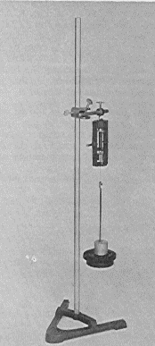
 |
| Fig. 2A. The PASCO apparatus, set up for static measurement of the spring force. |
|---|
The apparatus (Fig. 1) has a rotating shaft (G) with a high quality ball bearing (B). Rotate the shaft by turning the knurled section of the shaft (just above the bearing) by hand. A horizontal cross arm at the top of this shaft has a T-bar at its end (F). A bob of mass M hangs from this, stabilized by a bifilar suspension. An adjustable counterweight (C) balances the weight of the bob. The bottom of the bob (M) has a pointer. As the bob rotates, this pointer passes near a fixed reference pointer (A). The spring (H) supplies the centripetal force on the bob.
Static measurement of the spring's force. The apparatus also has a pulley (P) used only when you measure the force of the spring under static conditions (with the bob at rest). To do this, attach a string to the bob and run the string over the pulley to a weight hanger. Add weights (W) to the hanger until the bob's pointer aligns directly above the reference pointer. In this way you can determine the tension the spring exerts when the bob rotates at any radius (measured from the center of the shaft).
You may select different radii by repositioning the reference pointer base (at A). It may be varied over a range of a few centimeters.
Take data at three different radii of motion, one at the minimum radius, one at the maximum radius, and another between these extremes. We suggest that you make each static force measurement just before doing the dynamic measurements at that radius. Then you won't have to reproduce exact pointer settings (which might introduce error).
 |
| Fig 3A. The dynamic measurement. |
|---|
Dynamic measurements. Rotate the shaft and increase its speed until the bob's pointer passes directly above the reference pointer.
Then hold the speed constant while timing n revolutions. Count a large number of revolutions (at least n = 40) while measuring the total time with a wrist watch or stop clock. Choose n large enough to give the desired precision for the period and frequency.
You may change the mass of the bob by adding slotted weights to the top of the bob (up to 100 grams mass). Position them so that their slots point outward, and secure them well with the knurled nut, so they don't fly off.
Whenever you change the radius, or the mass of the bob, you must re-balance the rotating assembly. Do this by loosening the set screw at D and moving the counterweight (C) until the upper arm balances. Then tighten the set screw again before spinning the shaft.
You may vary the spring tension by substituting other springs, stronger, or weaker. Alternatively, you may connect a string, wire or paper-clip link to one end (E) of the spring, to make the spring tension smaller.
5B. USE OF THE CENCO APPARATUS:
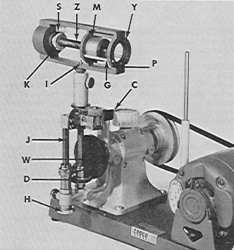 |
| Fig. 2B. The CENCO apparatus. |
|---|
The CENCO apparatus shown in Fig. 2B has a mass, (M), and a strong spring, (Z), in a sturdy cage (Y) that is driven by a motor with variable speed control. This apparatus does not allow any adjustment of the radius of motion of the mass, but does allow variation of speed and spring tension.
An adjustable screw (S) adjusts the length of the spring, and therefore the spring tension. It has an index and a micrometer scale. The speed is controlled by a friction drive. Rubber-faced wheel (D) presses against a flat-faced disk (W) that is driven by the motor. The adjustment screw 8 allows positioning of the friction roller to different radii, but this adjustment should only be made when the apparatus is running.
Older models may not have a belt guard, so keep your hands away from the belt and pulleys. Even the new models have exposed friction drive that can also be a hazzard. Before running the motor, be very certain that the centripetal force unit is firmly attached to the vertical shaft. Have your instructor check the apparatus. Keep the motor switch in your hand and prepared to shut off the motor quickly if anything goes wrong.
The frequency of rotation is determined by counting the number of revolutions in a given time. Some models may have a revolution counter.
 |
 |
| Fig 3B. The dynamic measurement. | Fig 4B. The speed index. |
|---|
 |
| Fig 5B. Static measurement of spring force. |
|---|
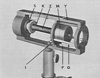
In figure 4B, the speed index pointer (P) points to a reference index (I) at the axis of rotation, and this may be easily seen even when the apparatus is rotating. As the spring stretches, the mass (m) presses against the pointer lever (Q), turning about its axis (O) and moving the pointer, (P).
Dynamic measurements: At a given spring tension, adjust the rotational speed until the pointer is at the index. Record the speed (revolutions/second) and the spring tension reading (S). Do this for the full range of spring tensions.
There's no provision for changing the mass in this apparatus.
Fig. 3B also shows the index line (M) scribed on the mass at its center of mass, and a micrometer scale on the frame, (Y), that you can use to determine the actual radius of the mass motion when the index pointer (P in fig. 4B) is at the index mark, (I in fig. 4B).
Calibration of the spring force: The entire cage assembly may be removed from the drive shaft. It has a provision to be suspended vertically with a weight hanger attached to the mass. For each position of the spring tension screw, record its setting (on the micrometer scale, (S), and also the amount of weight required to position the pointer (P) on the index mark, (I). In this way you can calibrate the spring tension indicator, (S).
One advantage of this apparatus is that the spring's center of mass is very near the axis of rotation. Therefore the dynamic tension of the spring is nearly the same as the static tension you measure when suspending the spring vertically. This is an interesting engineering design problem, and you may wish to analyze this yourself to see whether the design achieves its intended purpose.
6. OBSERVATIONS:
Here's a convenient way to arrange the columns of the data table:
Col.: 1       2          3                 4     5            6

TRIAL RADIUS  MEASURED   MASS  # OF TOTAL  REV/  COMPUTED     % DIS-
NO.           SPRING           REV  TIME   SEC.  CENTRIPETAL  CREPANCY
      R       FORCE      M     n     t     f     FORCE        between
              (Static)                           (Dynamic)    Cols 2&5
Obtain as wide a range of values of all of the variables as the apparatus will allow. The "measured centripetal force" labels the values obtained by direct static measurement of the force required to extend the spring to that radius. The "computed centripetal force" values come from calculation from the data in columns 1 through 3 by use of equation (2).
You will have to budget your time. If you used four different values of radius, and for each of these you took data on four different values of bob mass, you'd have 16 cases to measure. Then if you changed the spring tension four times, you'd have 64 total cases!
As a practical compromise, we suggest that you choose three different values of radii, and three different values of mass for each radius. Then do the same number of cases with a significantly smaller spring tension (by using a weaker spring, or by adding links to one end of the spring). These 18 cases represent the minimum data to achieve the purpose of this experiment. Try to obtain a large range of different frequencies of rotation.
7. ANALYSIS:
For reference we have numbered the important columns of the suggested data table. The other columns contain intermediate calculated values, not needed in this discussion.
We want to show whether the relations between centripetal force, mass, radius, and frequency agree with predictions from theory (Eq. 2). That relation tells us that the centripetal force is proportional to the mass and to the radius and proportional to the square of the frequency.
| [3 (from 2)] |
Fc = 4π2mRf2
Since for each R there's just one value of Fc (for a given spring), we rearrange the equation:
| [4] |
Fc/R = 4π2mf2
 |
| Fig. 6. Plot of centripetal force/radius vs. the square of frequency, with mass as a parameter. |
|---|
A graphical analysis provides a very meaningful and professional way to do this. Plot Fc/R vs. f2 for each of the four values of mass. If equation 4 is correct, this plot ought to look something like Fig. 3. If the points for each mass value fall on straight lines, you have demonstrated that Fc is proportional to f2, for each of the values of mass.
If this plot consists of straight lines passing through the origin, then you have demonstrated that Eq. 4 has no additional term on the right side.
Does the plot show the expected relationship? Comment.
The slope of each of the four lines should have the value 4π2m. [m represents the mass corresponding to each line, a different value for each line.] Calculate the experimental discrepancy.
You may verify the value of the constant of proportionality, 4π2, in many other ways. Here's another. Compare the last two columns of the data table (Cols. 2 and 5). Since you used the 4π2 factor in the calculation of column 5, the agreement between columns 2 and 5 confirms that factor, and the percent discrepancy between columns 2 and 5 measures how well you have experimentally confirmed Eq. 3.
Another way to verify the dependence of centripetal force on mass: Make another graph plotting Fc vs. M, using all of the data.
To verify the dependence of centripetal force on radius you will have to make a new graph, plotting Fc vs. R, using all of the data.
8. ERROR EQUATION:
You may easily obtain the maximum-error equation corresponding to equation (2) by the error propagation rules for multiplication and division:
| [5] |
ΔF   ΔM   ΔR     Δf
—— = —— + —— + 2 —— .
 F    M    R      f
The symbol ΔF means "error in F". [Derive this equation for determinate errors. Does it also hold for indeterminate errors?]
Use common sense and your own experience (doing this experiment) to estimate the size of each term on the right. Express them as percents. Which contributes the most the total experimental error? Which the least? Calculate the estimated percent maximum error (in the centripetal force) that you would predict for this experiment. Did your observed discrepancy lie within this estimate?
This error equation can help you in designing the experimental procedure. It can answer such questions as: "How many revolutions should you time so that the frequency will have an uncertainty no worse than that of the other measured quantities?"
The number of revolutions, n, resulted from simple counting, considered error- free. The time measurement for n counts might have instrumental error due to the clock (probably negligible) and reaction time in starting and stopping the clock. The equation f = n/t has error equation Δf/f = Δn/n - Δt/t, which reduces to approximately Δf/f ≅ -Δt/t. The minus sign simply means that for determinate errors, an error which makes t too large will make f too small. For indeterminate errors we remove the sign, since we assume that indeterminate errors have no bias with respect to sign.
Does Eq. 5 give an error estimate of almost the same size as your experimental discrepancy (Col. 6)?
9. QUESTIONS (PASCO Apparatus):
Starred (*) questions require more thought and understanding than the others.
(1) Derive a formula for the work done by centripetal force on the mass during one revolution.
(2) You obviously did work as you turned the shaft, keeping the speed constant. Yet the system's kinetic energy remained constant. Where did this work go?
(3) Suppose a suspended mass moves in a horizontal circle at constantly decreasing speed. Is the net force on this object radial? Why, or why not? Explain.
(4) Suppose that M = 500 gm, R = 15 cm and the static measurement of the spring force was 500 gm. You estimate an uncertainty in the time measurement of Δt = 1 second. For how long a time must you count revolutions so that the time measurement will contribute no more than 1% to the error in the centripetal force?
(5) Suppose that M = 500 gm, R = 15 cm and the static measurement of the spring force was 500 gm (equivalent). You estimate the uncertainty in the time measurement to be Δt = 1 second. For how long a time must you count revolutions so that the time measurement will contribute no more than 1% to the error in the centripetal force?
(6*) Suppose that the bifilar suspension were not vertical, say 5° off of vertical, and the experimenter didn't notice it. No other blunders were made in procedure or measurement. In the same spirit as question 6, calculate what determinate error this blunder would cause between the actual centripetal force and the measured value of centripetal force.
(7*) Suppose that the bifilar suspension were too short, and the experimenter didn't notice it. No other blunders were made. More specifically, suppose the suspension were so short that the spring made an angle of 5° with the horizontal. Assuming a procedure as done in this experiment, M = 500 gm, R = 15 cm, and the force of the spring, measured statically, was 500 gm. Clearly state any other assumptions you make and calculate the determinate error this blunder would cause between the actual centripetal force and the measured value of centripetal force.
10. QUESTIONS (CENCO Apparatus):
Starred (*) questions require more thought and understanding than the others.
(1) Derive a formula for the work done by centripetal force on the mass during one revolution.
(2) The motor obviously did work as it turned the shaft, keeping the speed constant. Yet the system's kinetic energy remained constant. Where did this work go?
(3) Suppose a rotating mass moves in a horizontal circle at constantly decreasing speed. Is the net force on this object radial? Why, or why not? Explain.
(4) Suppose that M = 500 gm, R = 15 cm and the static measurement of the spring force was 500 gm (equivalent). You estimate an uncertainty in the time measurement of Δt = 1 second. For how long a time must you count revolutions so that the time measurement will contribute no more than 1% to the error in the centripetal force?
(5) Suppose that M = 500 gm, R = 15 cm and the static measurement of the spring force was 500 gm. You estimate the uncertainty in the time measurement to be Δt = 1 second. For how long a time must you count revolutions so that the time measurement will contribute no more than 1% to the error in the centripetal force?
(6*) Suppose that the rotating shaft were not exactly vertical, say 5° off of vertical, and the experimenter didn't notice it. No other blunders were made in procedure or measurement. In the same spirit as question 6, calculate what determinate error this blunder would cause between the actual centripetal force and the measured value of centripetal force.
Text and line drawings © 1997, 2004 by Donald E. Simanek.