AM-2 The Kater Reversible Pendulum.
To accurately measure the acceleration due to gravity with a reversible physical pendulum.
| |||||||||
2. APPARATUS
One or more of the following:
- A Kater pendulum apparatus: a heavy bar with two precision knife-edges, weight at one end, and adjustable weight and rigid support for the knife-edges.
- A physical pendulum consisting of a center-weighted bar with accurately positioned holes and a knife-edge support.
- The student-friendly precision Kater pendulum: single brass bar with two holes and adjustable weight, with a knife-edge support. Tel-Atomic.
- A Kater pendulum built of available parts, as described below. Meccano parts were used in our model.
3. REFERENCES
Consult these references for the theory and experimtal methods before doing the experiment.
- Precision Kater Pendulum by Randall D. Peters.
- Student-Friendly Precision Pendulum by Randall D. Peters.
- Student-friendly Precision Kater Pendulum. TEL-Atomic Incorporated, 1999. Same material as references 1 and 2 above.
- The Compound Pendulum. Cenco Selective Experiments in Physics, Central Scientific Company, 1941.
- Miller, Dayton Clarence. Laboratory Physics, A student's manual for colleges and scientific schools. Ginn and Company, 1903. p. 80-85.
- Edward John Routh. The Elementary Part of a Treatise on the Dynamics of a System of Rigid Bodies. Macmillan and Co., 1891. p. 80-85.
- Capt. Henry Kater, F.R.S. An account of experiments for determining the length of the Pendulum vibrating seconds in the latitude of London. Transactions of the Royal Society of London. Read Jan 29, 1818. p. 33-102, plus figures. (Archived on the JSTOR database.)
4. HISTORY
In the 18th and 19th centuries much scientific interest focused on the problems of geodesy, in particular on determining the exact shape of the earth, the strength of the gravitational field, and the peculiar properties of the earth's magnetic field. Pendulums were often used to determine the gravitational field strength, using the familiar equation:
| [1] |
T = 2π√(L/g)
where T is the pendulum period, g is the gravitational field strength, and L is the length of the pendulum. This can be written:
| [2] |
g = 4π2(L/T2)
In 1815 Captain Henry Kater (1777-1835) devised a reversible physical pendulum design, and a data analysis method that improved the precision of determination of gravitational field strength by a factor of 10 to 100. Kater reported this to the Royal Society of London on Jan 29, 1818. The Kater pendulum became the standard for such measurements for over a century.
Pendula consisting of a bob on a string required accurate determination of the length measured from the support to the center of mass of the bob. This was difficult to do precisely. Kater's method cleverly used several innovations: (1) A solid (physical) swinging body, (2) use of precision knife-edge suspension points on the pendulum itself, (3) reversing the pendulum, allowing determination of the period of swing about two (or more) different points. These features reduced the data to just two accurate kinds of measurements: (1) periods of swing, and (2) one length, easily and precisely measured between two knife edges, firmly fixed on the solid pendulum itself.
4. PROCEDURE
A. Kater style pendulum.
This pendulum is a heavy bar (usually a meter or more in length) with two knife edges permanently fixed on the pendulum bar itself, and a large mass located near one end of the bar. A second, smaller, mass is adjustable in position. The procedure is to adjust the position of the smaller mass until the pendulum's period is precisely the same for each of the suspension points. When this condition is achieved, the pendulum period is given by equation (2) where L is the distance between the knife-edges. One advantage of the Kater design (compared to the others described below) is that the distance between the two knife edges is adjustable, and may be very accurately determined with appropriate measuring instruments.
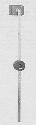
B. Cenco style physical pendulum.
This pendulum has a heavy bar (a meter in length) with a large number of holes that may be used as suspension points, the knife-edge being part of the rigid support mounted on a wall. A large mass is located at the center of the bar. The pendulum's period is determined for each of the suspension points, on both sides of the center. Typical results will look something like this:
 |
| Fig. 2. Graphical analysis of data from a Kater pendulum. [CENCO] |
|---|
A horizontal line is drawn for a particular period, intercepting the curves at S, O', O and S'. The distance between S and O is l, as is the distance between S' and O. Since l isn't very distinctive in HTML documents, we will call it L. This is the length that relates to the period by eq. (2).
Important note: Refer to Fig. 1. Suppose we measure lengths from the left end of the bar. When the pendulum is suspended from holes to the left of its center, the lengths are to the left side of the holes. When the pendulum is reversed, the lengths are measured to the right side of the holes. Of course the starting (zero) point for these measurements is arbitrary. If the holes are accurately spaced one can conveniently use the spacing of the holes as a unit of measure. But if you do this, be sure to add the diameter of a hole to the positions for the holes to the right of center. This correction can be done once, at the very end of the calculation of L. The diameter of holes in Meccano strips is 0.156 inch.
C. TEL-Atomic Kater pendulum.
This small pendulum was originally sold by the TEL-Atomic company. It is described in references 1, 2 and 3. The pendulum is a simple brass strip 37.40 cm long, with a hole near one end, and another hole accurately positioned so that its suspension point is 24.810 cm from the first hole. Of course this is not adjustable by the user. A plastic sliding weight is provided to adjust the two periods to equality. The equations, and method of data analysis is the same as that for the standard Kater pendulum.
This apparatus has several problems. The brass strip has a tendency to wobble. The knife edge must be secured solidly. It is not good enough to use a laboratory stand, even a sturdy one. Secure the knife edge to a solid wall.
D. Meccano model of the physical pendulum.
|
Steel construction set "perforated strips" have very uniformly located holes. "English" sets (Meccano, Erector, Märklin) have holes spaced 1/2 inch apart. "Metric" sets (Eitech, Merkur, etc.) have holes spaced 1 cm apart. Temsi sets have a strange hole spacing that is 6/10 of an inch, and these are best avoided for this experiment. Meccano strips with 25 holes were used for our model. The fact that the holes in these "toys" are precisely spaced is the main advantage of using them, compared to, for example, hardware store items, or drilling holes yourself.
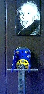
Use two such strips, with extra weight bolted at the middle, so the strips are about 1 inch apart. We used a short strip of steel spine from auto windshield wipers as a suspension "knife-edge). This suspension was rigidly mounted to a good magnet so that it could be placed on a steel wall, filing cabinet, or steel-backed blackboard. Be sure to use a magnet that has poles on one face only, for we don't want the swinging steel pendulum to be damped by the magnetic field. Three bolts were affixed to the magnet with epoxy, spaced to interface the magnet to the plates of the construction set parts. It's a good idea to provide some adjustment to level the knife-edge, yet keep it solidly in place. (In Fig. 3 we show Merkur (metric) parts for the suspension, and Meccano (English) parts for the pendulum.)
This design is easily adapted to either of the above methods of analysis. For the "Cenco" method of analysis, the weight is at the pendulum's midpoint. The mass should be located near one end for the Kater analysis, and a small office "binder clip" is used as the adjustable-position mass. In the Kater analysis, periods are measured about only two holes, chosen so that their periods can be made equal, or nearly so.
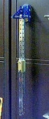
E. Meccano model of the physical pendulum.
|
Kater's original pendulum had the mass at one end, and with two knife edge suspensions, Kater adjusted one edge until the periods were exactly equal about either suspension point. We can duplicate that with Meccano parts as shown in Fig. 4. Two 25 hole strips are 1/2 inch apart, with stacks of 3 hole strips (or other extra weight) at one end. Near the other end the strips are stabilized with a 1/2 inch spacer. (Aluminum screw posts are handy here, and are available at stationary stores. They have 6-32 standard threads.)
Find the period of swing about the unweighted end (hole zero). Then find the periods at holes 17 through 21. These will include periods larger and smaller than that at hole zero. Now use mathematical interpolation to find the distance between hole zero and a point where you could put a hole to obtain the same period as at hole zero. Any mathematics software can do this nicely, for example Mathematica or Maple. You can download this Mathcad worksheet file to do this process easily. It works with Mathcad versions 2.0 or higher, but may have irregular text formatting on higher numbered versions. This may easily be edited for better apearance.
The equation required is:
| [3] |
g = (π/T)2L
Where L is the distance between the points of equal period.
F. Fine points.
The "best" period to choose for the final calculation of part (B) is one that gives a period about equal to the period for suspension about a point about 1/3 of the distance from one end to the center of mass. This gives the smallest uncertainty in the result for g.
For the TEL-atomic and Meccano models, time about 50 swings at each suspension point.
When analyzing the data as in Fig. 2, you cannot usually "get by" with an ordinary graph measurement, unless the graph is made very large. It's best to use a mathematical software package to interpolate values along each of the four portions of the curve which intersect the horizontal line. Using Mathcad's © parabolic spline function, and the Meccano model, we achieved a result good to about 1/3 percent.
If you use English standard construction set parts, don't forget to convert inches to metric units when calculating your answer.
Using the Kater method, it's not entirely necessary to achive exactly equal periods about two suspension points. One can move the adjustable weight, measuring periods at several recorded positions of the weight for each of the two suspension points. A plot of the periods vs. weight position will give two intersecting graphs, from which the true period at the point of "period equality" may be determined. That period may then be experimentally confirmed.
When building your own pendulum, consider these important requirements:
- The support must be massive and absolutely unmoving.
- The knife edge must not "wander" in position on its support.
- The pendulum should swing in a plane, without wobbling about its own length axis. This is why the Meccano model has two identical perforated strips separated by about an inch. An earlier prototype model with a single strip wobbled a lot. Even some commercial versions have a tendency to wobble if the swing is not started carefully.
- You know that you have support problems when the pendulum comes to a stop in less than 50 swings. It is losing energy somewhere, and the support is the place.
- Use only small amplitude swings, less than 5°.
5. QUESTIONS
(1) Show that the relative uncertainty in the result of this analysis is given by:
| [3] |
Δg/g = (ΔL/L) + (2ΔT/T)
(2) How much error would be introduced if the pendulum swings had amplitude of 10°? Would this matter?
(3) How much error would be introduced if the pendulum support were not securly mounted, and moved sidewise in resonance with the pendulum swing, with an amplitude of 2% of the pendulum's length? Would this matter?
Text and color photos © 2004 by Donald E. Simanek.