S-3 LADDER AND CRANE BOOM PROBLEMS
To investigate static equilibrium situations in which a rigid bar, tilted to the horizontal, is in equilibrium under the action of non-concurrent forces. To analyze these situations using forces and torques.
2. APPARATUS:
(1) Ladder model: Square array of laboratory rods, firmly attached to the table; model ladder; three spring balances; weight hangers; slotted weight set (small size weights).
(2) Crane model: Two heavy one-meter rods; parallel clamp; hook collar; large capacity spring balance (10 kg); two lengths of chain (or heavy, smooth rope); large weight hanger; large slotted weight set; right angle clamp for bottom hinge; special boom element with internal spring scale; heavy duty ball bearing pulley with collar.
(3) Suspended bar: Square array of laboratory rods, firmly attached to the table; metal bar with holes; three spring balances; weight hanger; slotted weight set (small size weights).
3. BACKGROUND:
Read the theory section of experiment S-1.
4. ADDITIONAL THEORY:
TENSION. The tension exerted by the end of a string or wire is simply the size of the force that end of the string exerts on the object to which it is attached. By Newton's third law, the other object exerts an equal and opposite force on the string. Tension forces are parallel to that end of the string. A string is incapable of exerting appreciable force perpendicular to itself, at its end; because of its limpness.
 |
| Fig. 1. Tension in a string. |
|---|
TENSION IN A RIGID ROD. The tension at the end of a rod is the longitudinal component of the net force exerted on the end of the rod. (We shall use "longitudinal" to mean "parallel to the rod," "transverse" to mean "perpendicular to the rod.")
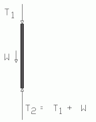
The tension is not necessarily the same at both ends of a rod. Consider the simple case of a vertical rod under tension. The tension at the bottom equals the tension at the top plus the rod's weight.
 |
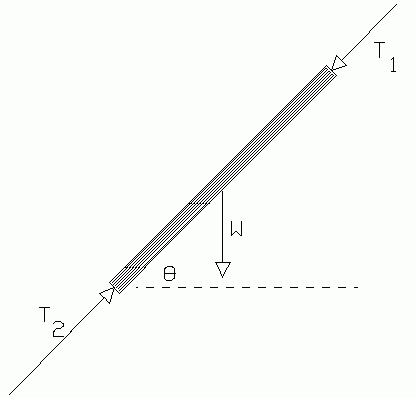 |
| Fig. 2. Vertical rod. | Fig. 3. Tilted rod. |
|---|
The rod's weight also figures in when the rod is tilted. This is very quickly analyzed by considering the longitudinal force components only, for if the rod is in equilibrium, they must add to zero. Let T1 be the longitudinal component of all forces acting on the top of the rod. This is the tension at the top of the rod. Let W be the weight of the rod, acting downward at its center of mass. Let T1 be the longitudinal component of all forces acting at the bottom of the rod. For this simple example, we will assume no other forces act on the rod. Then
T2 = T1 + W sin θ
Of course, if there were other forces on the rod, perhaps acting at various points, their longitudinal components would have to be included in the equation, with proper signs.
TERMINOLOGY:
The sum of a set of forces is, of course, the vector sum, and is sometimes called the resultant of the forces.
The equilibrant of a set of forces is the negative of the resultant. The equilibrant is that additional force which would be required to bring the system into equilib- rium.
5. SITUATIONS TO INVESTIGATE:
Two situations from "everyday life" make instructive exercises in statics. They are
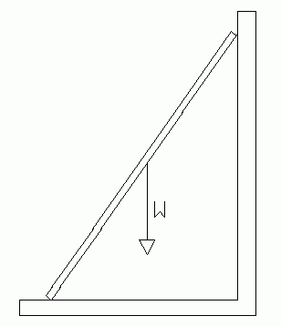
(1) A ladder propped up against a wall
(2) A simple crane boom for lifting and relocating heavy objects.
 |
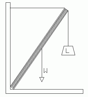 |
| Fig. 4. Ladder. | Fig. 5. Crane. |
|---|
Physics textbooks have many examples and exercises relating to these two situations.
As the diagrams show, the two have a great similarity. We will take advantage of this to discuss an analysis procedure which applies to both.
The figures below illustrate the similarities. In both cases the rigid, but movable element makes an angle with the horizontal, which we will call θ. The bottom of this rigid element is supported by a force which has two components which we will call V (for vertical component) and H (for horizontal component.)
In the ladder problem it is usually assumed that friction at the top of the ladder is small enough to neglect. So the wall exerts a force on the ladder which is strictly horizontal.
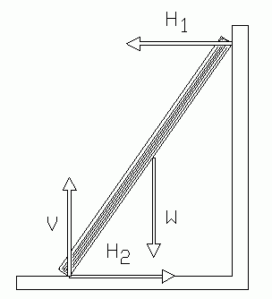 |
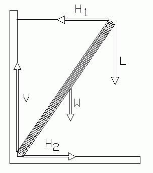 |
| Fig. 6. Forces on a ladder. | Fig. 7. Forces on a crane. |
|---|
The crane boom, set up as illustrated, has a horizontal force at the top supplied by the tension in the horizontal cable. In both problems there are only two horizontal components on the rigid element, so these must be equal in size and opposite in direction to produce equilibrium. We will label their size H. Therefore |H1| = |H2| = |H|
The weight of the rigid element cannot be neglected. It can be treated as a downward force acting at the center of mass of the rigid element. We label it W.
Finally, the rigid element may support a load. In the ladder, this is the extra weight of the man standing at some point on the ladder. In the crane boom it is the load, usually hung or attached at the upper end of the boom. In either case we will label it L, for load.
6. PROCEDURE:
Preliminary study of spring balance:
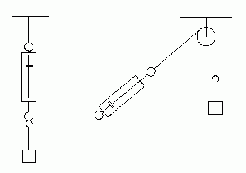 |
| Fig. 8. Method to study the spring balance. |
|---|
Spring balances are designed to read weights correctly when they are hanging straight down. In this experiment we may choose to use them in other positions, so we must first find out how to correct the readings for angle.
(1) Use a ball-bearing pulley, weight hanger, string, and spring balance arranged as shown in the figure. The angle may be measured with a goniometer or a large protractor.
(2) Load the weight hanger so the spring balance reads a value about in the middle of its range. Be sure you use a pulley strong enough for this load. Don't forget that the mass of the hanger is part of the load.
(3) Take data for spring balance reading vs. angle for angles from zero to 180 . Be sure to "jiggle" the system before each reading to avoid effects of frictional drag in the pulley, and in the spring balance itself.
(4) Plot this data. If you happen to have a sheet of polar coordinate graph paper, use it to make another graph of the same data.
(5) The data was taken for fixed load. What would you expect to happen if the load had been significantly larger or smaller? State how your graph could be adapted to give correct readings for any load within the spring balance's range. Check your hypothesis with a 50% greater load at angles of 45, 90, and 135 degrees.
A. Ladder Model
This may be constructed with a special metal beam (which represents the ladder) suspended in a square framework built from heavy laboratory rods. Spring balances attached to wires supply forces which represent the wall thrust, and the vertical and horizontal components of the forces the ground would exert on the foot of the ladder. The weight of a person on the ladder is represented by a load hung from one of the "rungs".
Set up the model as shown in Fig. 9. Do not ignore the weight of the "ladder" beam. Remove it and weigh it on a balance. Its center of mass is marked by an indentation labeled "C.M." Check this yourself.
Keep the load, L, within a range from 1 to 5 times the mass of the ladder. Be sure that V is exactly vertical, and H and H horizontal.
B. Model Crane
Set up the crane boom as shown in Fig. 3, being certain that the supports are rigid, and the lower end of the boom is not clamped tightly. The boom must be free to move in a vertical plane, but prevented from moving in a horizontal plane (rotating around the upright rod.)
The boom will be loaded heavily, so pay attention to good "engineering design" to prevent collapse of the structure. Do not suspend the load far above the floor, and keep your feet out from under it. The impact of one kilogram falling on your toe from one meter high is a sensation you would not soon forget. [It could break a toe.]
Keep the weight of the load between 1 and 5 times the weight of the boom. Be sure the chain attached to the top of the boom is exactly horizontal.
Measure the dimensions of the system, and read the thrust tension on the boom scale. Also note the amount of the load (including the chain and hanger.) Before the system can be analyzed it is necessary to know the weight and center of mass of the boom. The boom has a built-in spring balance, and it shortens under load, thereby changing the position of its center of mass. It is necessary to locate the center of mass when the boom is compressed to the same reading it had in the experiment. This may be accomplished by using a strong wire to tie the boom in its contracted position, removing it from the system, and finding its balance point.
If there is time, investigate other situations with different load, boom angle, etc. Try a case where the upper cable is not horizontal.
C. Suspended Bar.
This is similar to the ladder model, and may be analyzed in the same way. The difference lies only in the directions of the forces, and in the fact that this bar is under stretch tension rather than compressional tension. The set-up is inherently stable and therefore easier to set up.
In Fig. 11 the forces are labeled with letters corresponding to those used in the other two kinds of apparatus. This will allow us to describe an analysis method suitable for all three. W represents the weight of the bar (which you must measure) acting at the bar's center of mass (which you will also determine separately).
Be sure L is vertical and H and H are horizontal. Keep the load, V within a range from 1 to 5 times the mass of the bar.
7. GENERAL PROCEDURE FOR ALL SYSTEMS:
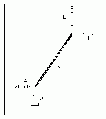 |
| Fig. 11. Suspended bar. |
|---|
For brevity we will refer to the system's rigid element (boom or ladder) as the bar.
(1) The system must be disassembled to remove the bar and measure its mass and center of mass. This can be done before or after the remaining steps. If you are using the crane boom this is best left until last, since the center of mass must be determined when the boom is exactly the same compressed length as in the main part of the experiment.
The bar's mass may be measured with a beam balance of sufficient capacity. The center of mass may be determined, as in experiment S-2A, by suspending the bar from spring balances at each end.
(2) The load, L, is known from the mass you placed in the weight hanger. Don't forget to include the weight of the hanger.
(3) The force, H1, is directly read from the spring balance. Jiggle the system before reading this, to be sure the system freely settles into a true equilibrium, independent of hidden frictional forces.
(4) In the ladder model V and H2 are also read from spring balances. In the crane boom model you can directly read the boom tension; this being the tension at the top end of the boom.
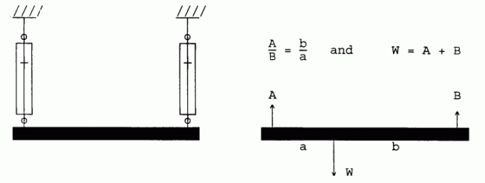 |
| Fig. 12. Measuring the mass and center of mass of the bar. |
|---|
(5) Accurately measure the tilt angle, θ, of the bar. Usually the best way is to measure the lengths of the legs of a right triangle having the bar as hypotenuse; then use the tangent relation from trig. The length of the bar must be measured also.
8. ANALYSIS:
We will assume the principles applicable to a body in equilibrium:
(a) The sum of the forces on the body equals zero; thus the sum of components of these forces along any axis also equal zero.
(b) The sum of the torques on the body equals zero, about any arbitrarily chosen torque center.
Our object will be to see how well the experimental data agree with these principles. You will do this by making certain calculations, using these principles, and using only data on L, W, H, θ, a (from center of mass measurement), C and B. (For the boom, C = B). You will then see how consistent are the results from these values with your other measurements. In each calculation, write the error equation. See whether the discrepancies between calculated and measured values are consistent with the error analysis.
(1) Since H1 and H2 are the only forces with horizontal components, and they are themselves horizontal, then they must be equal in size and opposite in direction. If you used the ladder model you measured both of these and can check how closely they were equal. From here on, we will simply refer to their size as H.
(2) Consider the vertical components. You should have V = L + W. If you used the ladder model you can check this result against your measured value of V.
(3) Choose a torque center at the bottom end if the bar and calculate the value of H1. Compare with your measured value(s).
(4) Choose a torque center at the top end of the bar and calculate the value of V. Is this consistent with the value(s) of analysis item (2)?
(5) Look at at the forces at the very top of the bar. Find the sum of all forces acting there, on the bar. Call this sum U.
Ladder: U = H
Suspended bar and boom: U = H + L
Use your experimental values of H and L.
(6) Find the angle between U and the bar. Call it φ.
(7) (U cos φ) should be the tension at the top of the ladder. If you used the crane boom, compare this with the tension read from its internal spring scale.
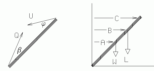 |
| Fig. 13. Analysis of the bar. |
|---|
(8) Find the sum of all forces acting on the bottom of the bar. Call this sum Q
Q = V + H2
Use your experimental value of H (and of V, if you used the ladder model).
(9) Find the angle between Q and the bar, call it β.
(10) Q cos β should be the tension at the bottom of the bar. Note that it is not the same as the tension at the top of the bar, that is,
Q cos β ≠ U cos φ
But, doesQ cos β = U cos φ + W sin θ ?
or, doesQ cos β = U cos φ + W sin θ + L sin θ ?
Should it? Explain.
(11) From equilibrium principles, complete the following expression by filling in the missing term(s).
Q sin β = U sin φ + (..............)
How well do the data confirm this relation?
Text and diagrams © 1997, 2004 by Donald E. Simanek.