S-5 FORCES AND TORQUES
1. PURPOSE:
(1) Study static equilibrium under the action of several forces.
(2) Test whether the forces on a body at rest add to zero.
(3) Test whether the torques on a body at rest add to zero.
2. APPARATUS:
Drawing board, four pulleys with table edge clamps, four weight hangers, metric mass set (colloquially called "weights"), fiberboard "body" with four holes and attached strings, ruler, draftsman's triangle, small mirror, 17 x 22" drawing paper.
3. BACKGROUND:
Read the chapters on vectors and torques in any physics textbook.
4. NOTE ON UNITS:
You can avoid unnecessary multiplications by 9.8 m/s2 or 980 cm/s2 by expressing all weights in grams. This "convenience unit" is sometimes called the "gram-weight."
5. THEORY:
Forces. Many measurable quantities in physics obey the laws of vector algebra, and force is one example. The vector sum of the forces on a body is important because it determines whether the body will move, and how it will move.
Torques. Each force has an associated torque. The size and direction of a force's torque depends on that force and on its geometric relation to a chosen reference axis. When analyzing torques, one may arbitrarily choose any axis as a reference. When all forces lie in a plane, we usually choose an axis perpendicular to that plane. The point where the axis crosses the plane is called the center of torques. The vector sum of the torques on a body is important because it determines whether, and how, the body will rotate.
Calculation of a torque. We'll restrict this discussion to two-dimensional problems, where all of the forces lie in a common plane. Arbitrarily choose a point to be the center of torques and mark it on the scale diagram of forces. Extend the line of action of each force far enough so that you can draw a line from the center of torques perpendicular to the line of action. The length of this perpendicular line is called the lever arm of that force. The size of the torque is the product of the size of the force and the size of the lever arm.
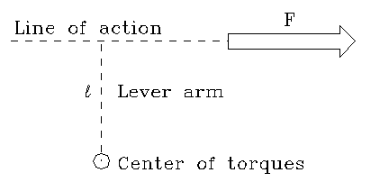 |
| Fig. 1. Torque due to a force. The torque due to force F is the product of the sizes of the force and the lever arm ℓ. This example is a clockwise torque. |
|---|
In two-dimensional problems the directional sense of a torque may be clockwise or counter-clockwise. The sense of the torque is easily determined by considering what direction the lever arm would rotate if it were a stick pivoted at the center or torques and "pulled" by the force. Conventionally, clockwise torques are assigned a negative sign, and counterclockwise torques are positive.
In this experiment you will study the special case of a body at rest, having zero velocity. Such a situation is called static equilibrium. When a body is in static equilibrium the sum of all forces acting on that body is zero. Also, the sum of all torques acting on that body is zero, about any axis.
Note: The torque of a force is not a unique value, but depends upon the chosen center of torques. The torque represents the 'tendency' of the force to produce rotation about the center of torques. If a force passes through the chosen center of torques, it has no tendency to rotate the body around that point, and its torque about that point is zero. One should not say "The torque of force F is ..." but rather say, "The torque of force F about axis (or point) ... is ..."
Static Equilibrium describes the condition in which a body is at rest with respect to a frame of reference. When a body is in static equilibrium:
(1) The vector polygon of all forces acting on the body is closed. The sum of the vectors representing the forces is zero.
(2) The sum of the components of force along any axis is zero.
(3) The sum of all torques acting on the body is zero, about any chosen axis.
6. GENERAL INSTRUCTIONS:
Read this section before beginning section 7, Procedure.
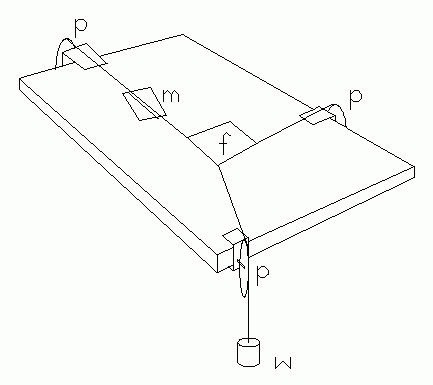 |
| Fig. 2A. Drawing board force table. |
|---|
In Fig. 2A:
f fiberboard rectangle
p pulleys
w one of the weight hangers
m mirror.
The force table apparatus demonstrates the addition of forces acting on a body, in two dimensions. In this experiment the force table is an ordinary drawing board with pulleys attached at its edges. [If the laboratory table top is not too thick, the pulleys may be attached directly to it, and you won't need the drawing board.] Tape a sheet of plain paper (about 17 by 22 inches) to the board. A rectangle cut from fiberboard is the "body" to which forces are applied. The forces are applied by strings which run over the pulleys to different sized weights on weight hangers. Figure 2 illustrates the arrangement.
Take care to adjust the pulleys so the strings pass straight over them, ensuring minimum friction. Use enough weight on the hangers so the strings are nearly parallel to the table and do not sag much. Why is this important?
When you achieve equilibrium of the body, the directions of the forces lie along the direction of the strings. These directions must be transferred accurately to the drawing paper. Do this with the aid of a small mirror. Place the mirror face up on the table under a string, then sight from above, moving your head until the image of the string seen in the mirror is directly below the string and therefore hidden by the string. With your eye in this position, make a pencil mark directly under the string at each end of the mirror (so the mark is also hidden by the string). This procedure ensures that the experimenter's eye is directly above the string and that the line of sight is perpendicular to the mirror, thereby eliminating errors due to parallax. Remove the mirror and draw a line through the points with a ruler. The line will lie accurately along the direction of the string and therefore records the direction of the force due to that string.
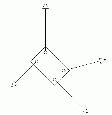 |
| Fig. 2B. Non-concurrent forces. |
|---|
Do this for each string, then sketch the position of the fiberboard rectangle onto the paper. Remove the drawing paper. Subsequent analysis is done directly on this paper.
Draw the lines of action of the forces on the sheet. Now choose a scale to represent forces as lengths. For example, you might choose 1 cm to represent 10 gm. Choose a scale large enough to give good precision, while still keeping the diagram within the sheet of paper.
Errors in vectors. One source of error in this experiment is the starting friction in the pulleys. The size of this error is estimated by determining how much the weight on a weight hanger can be varied without disturbing the equilibrium. Do this, and find the full range of the uncertainty in each force. The "best" value of this force is at the center of this range. Record the uncertainty of the force and its percent uncertainty. Investigate and record the error in the angle in the same way.
7. SITUATIONS TO INVESTIGATE:
Each different situation is recorded on a separate sheet of drawing paper. The force and torque analysis for each situation is then done directly on that work sheet.
Use 200 to 500 gram weights on the hangers. Avoid situations where all hangers have the same weight. Try for a representative, general case. Avoid special situations such as 30°, 45°, or 90° between the forces.
(1) THREE FORCES. Set up an equilibrium situation in which only three forces act on the body. Transfer the forces to the paper.
(2) FOUR FORCES. Use a new sheet of paper. Set up an equilibrium situation in which four forces act on the body. Again choose a general case, and investigate the errors as before.
8. ANALYSIS:
For the three force case, carry out analyses (1) and (2). For the four force case, do analyses (1), (2), and (3).
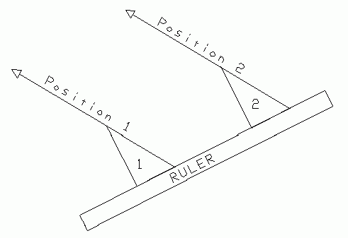 |
| Fig. 4. Moving a line parallel to itself with ruler and triangle. |
|---|
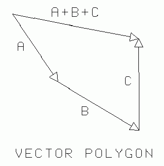
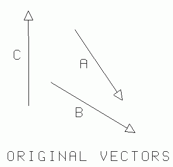
(1) POLYGON METHOD. When adding vectors by the polygon method you must "move" the vectors parallel to themselves. This is easily done with ruler and triangle as shown in Fig. 4. Lay an edge of the triangle along the vector, then lay a ruler along another edge of the triangle. Hold the ruler firmly in place on the paper and slide the triangle along the ruler until its edge falls where you want the vector relocated. Draw the line of action of this vector along the edge of the triangle.
Fig. 5. illustrates the addition of three vectors by the polygon method. Note particularly that the original vectors do not need to have their tails at the same point. The vectors may be assembled into the polygon in any order, since vector addition is commutative. In the case of static equilibrium, which you are investigating, the vectors will very likely add to nearly zero, so that their resultant A+B+C will be very small relative to the vectors being added.
 |
 |
| Fig. 5. Polygon method for adding forces. | |
|---|---|
On a clear area of your work sheet, transfer the forces onto a vector polygon and test whether the polygon closes. It probably won't close perfectly. Why not? What is the size and direction of the additional "error" vector required to close the polygon? Is its size consistent with the error caused by error in each of the individual forces? This last question will require considerable analysis, and a consideration of how to do an error propagation calculation for vectors. Carry out this analysis for both experimental situations.
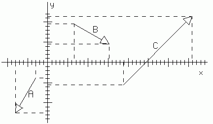
(2) ANALYTIC METHOD. For each situation, choose arbitrary X and Y axes, and resolve the vectors into components along these axes. It is not necessary to move the original vectors on the sheet. Merely drop construction lines (dotted lines in Fig. 5) from their heads and tails, perpendicular to the chosen axis. Measure the sizes of the components and record these in tabular form. Numerically add the X and Y components separately to obtain the X and Y components of the resultant. Is the resultant zero? If not, is its size consistent with the resultant found in analysis step (2)? Estimate how much additional error is introduced into the drawing by construction and measurement steps.
 |
| Fig. 6. Components of vectors by the analytic method. |
|---|
Example: Refer to Fig. 6. Find the components of vector B. Its head is at coordinate (16.2,4.7) and its tail is at (6.5,9.8). Its x component is therefore 16.2 - 6.5 = 9.7, and its y component is 4.7 - 9.8 = -5.1. Notice how the y component came out negative. The vector is pointing "downward" (negative) with respect to the y axis, but "forward" (positive) with respect to the x axis.
Exercise 1. Refer to Fig. 6. (a) Find the components of vector A. (b) Find the components of A+B. (c) Find the components of vector C. (d) Find the components of A+B+C.
Good "bookkeeping" is essential when doing these problems. For example, the following table keeps track of the numbers of exercise 1. We have only filled in part of it: you may fill in the rest.
 |
| Fig. 7. Good bookkeeping. |
|---|
The size (magnitude) of a vector is always positive, and may be found by using the Pythagorean theorem if the components are known. The angle of a vector is conveniently specified with respect to the positive x axis, measured counterclockwise. If the components are known, the angle is arctan(Vy/Vx).
Note that your electronic calculator always returns an angle less than 90°, which you must convert to correctly indicate the quadrant in which the angle lies. Obviously the calculator cannot do more for you because of the ambiguity of sign: Vy/Vx has the same sign (positive) in first and third quadrants, and in the second and fourth quadrants the sign is negative.
(3) MOMENTS (TORQUES). On the worksheet of procedure (2), choose an arbitrary center of torques somewhere on the sheet. Construct lines from this point perpendicular to each force. In some cases you may need to extend the line of action of a force to meet this perpendicular. The lengths of these perpendicular lines are the lever arms of the forces. Refer again to Fig. 1 for the method.
To gain the maximum instructional value from this exercise, we ask you do to it two ways:
(1) The "best" method. Choose a center of torques where the lines of action of two forces cross. This eliminates two torque calculations, saving you time, and reducing some chance for measurement errors.
(2) Instructive method. The choice of center of torques is arbitrary. If the sum of torques is zero about one center, it will be zero about any other center. To appreciate this fact, deliberately choose a center of torques which is not on the line of action of any of the forces. Now see whether they add to zero. This will also be instructive from the point of view of error analysis, for there are errors associated with a length and lever arm for each of the four forces, that is, eight measurements which may have experimental error.
9. QUESTIONS:
(1) If the weights of the weight hangers were exactly the same could their weights have been neglected in the computations? Explain.
(2) Devise a mathematical proof of the following proposition: "When only three forces act on a body in equilibrium, they are either all parallel, or they pass through a single point."
(3) Prove mathematically that if the sum of torques on a body is zero about some particular axis, it must be zero about any axis.
Text and drawings ©: 1997, 2004 by Donald E. Simanek.