 |
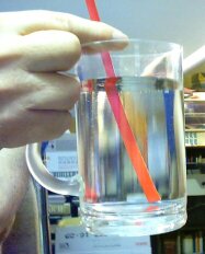
| A pencil in water. This is slightly deceptive, for the sides of the container act as a cylindrical lens. |
|---|
L-1 GEOMETRY OF RAYS
1. PURPOSE:
To study the laws reflection of refraction of light, and to use geometric methods for applying these laws.
2. EQUIPMENT:
Cylindrical mirror and lens modelsCork board and pins (or small electric lamps)
Compass and straightedge.
3. THEORY AND PRE-LAB REVIEW:
The law of refraction has been known since ancient times. Ptolemy (about 75 CE) described it in his book on optics. When a stick, say a pencil, is partly submerged in a glass of water, the stick seems to be bent. These early scientists did not believe that the stick was really bent by the water, but rightly assumed the light rays were bent as they emerged from the water. Ptolemy explained it in that manner, though his statement of the law of light bending (n1θ1 = n2θ2) was not quite correct. [It is approximately true only for small angles.] Also, as the color picture shows, the character of the image one sees can also be partly due to the refraction at the walls of the container.
We now know the law to be:
| [1] |
|---|
n1sin(θ1) = n2sin(θ2)
where the angles θ1 and θ2 are measured from the ray to a line perpendicular to the surface, and the constants n1 and n2 are properties of the media, called their indices of refraction. The line perpendicular to a surface is called the surface normal, or simply the normal. (1)
 |
 |
| Fig. 1. Refraction of a ray. | Fig. 2. Refraction at a curved surface. |
|---|
Consider a single spherically curved surface S separating two media of different refractive index. Our problem is to find the direction of the emergent ray, when given the direction of the incident ray. Or, given the emergent ray, we must find the incident ray. This type of problem may be solved with ruler and compass by following the steps outlined below.
 |
| Fig. 3. Incident and emergent angles. |
|---|
(2) Mark off the length AP representing n1 along the radial line. Likewise mark off the length PB representing n2.
 |
| Fig. 4. Steps 1 and 2. |
|---|
(4) With a compass, draw an arc of a circle of radius R centered on B. Draw the line PE tangent to the circle. This is the emergent ray, since it forms a leg of a right triangle satisfying R = n2(sinθ1)
 |
| Fig. 5. Steps 3 and 4. |
|---|
 |
| Fig. 6. Similar triangles. |
|---|
Example:
To show that this procedure works also in the case where n2 is less than n1, we choose n1 = 1.4 and n2 = 1. The line AP is 1.4 times as long as the line PB.Notice that in all of the constructions the direction of the surface curvature plays no role at all. The angle of refraction at a particular point is independent of the amount or sense of the curvature at that point.
 |
| Fig. 7. Ray from higher to lower index. |
|---|
Critical Angle. The only time you will run into "difficulty" with this construction method is when R is greater than the smaller value of n. In this example, if the incident ray were at such an angle that R came out to be l or greater, you can't construct the emergent ray. In fact, in this situation he ray can't get across the surface and is totally reflected from the surface. A little thought will convince you that the refraction law predicts the same thing. The way we measure angles, the incident and refracted rays must make angles to the normal of no more than 90°. Anything greater would be meaningless for refraction. The angle 90° is allowed, and is the largest allowed; it corresponds to a ray moving along the surface. When one ray is 90°
n1sin(θ)1 = n2sin(θ)2
so, sin(θ1) = n2/n1
So we see 2 can be 90° only when n1 is greater than n2. In that case, the last equation gives the corresponding value of incident angle, 1, which is the largest incident angle, which can produce a reflected ray. It is called the critical angle. Larger incident angles give only reflection.
 |
| Fig. 8. Refraction at several surfaces. |
|---|
So, if you know the radius of curvature of a surface, the refractive indices, and the angle of the incident ray and where it strikes the surface; you can then always find the angle of the emergent ray. And if the emergent ray goes on to strike another surface, you could repeat the process, to find the emergent direction from that surface, and so on. It might become tedious, but the principles are straightforward. In fact, when high-speed computers are employed for lens design, this is exactly the mathematical method used.
Each curved surface bends (deviates) the ray. Fig. 10 shows the refraction at the surfaces of a compound lens. After passing through the first two surfaces the total angle of deviation, δ, is given by δ = α + β. (2) Deviation angles are additive. The total deviation when a ray crosses two surfaces is the sum of the deviation produced by each surface. Deviation angles do not tell the whole story, though. You can see that it is important to know the lateral position of a ray, at the point where it strikes each surface.
PRACTICE EXERCISES:
(1) Use the geometric method to find how each of these three rays in Fig. 9 is bent at the air-to-glass surface. Take the index of refraction of the glass to be 1.5. You may do this directly on this page, or on a copy or tracing of the diagram.
 |
| Fig. 9. Rays entering an air to glass interface. |
|---|
(2) Use geometric construction and the refraction law to find the critical angle for a ray passing from glass (n = 1.5) to air (n = 1).
4. PROCEDURE:
An assortment of lens and mirror shapes are available (specimens), made of glass or plastic. A corkboard and pins may be used in the following manner to trace the paths of light.
Lay a sheet of plain paper on the corkboard. Place the specimen (mirror or lens) on the paper, and trace its outline. Do not move it thereafter. Put your eye on a level with the specimen and look at the light emerging from it. Place a pin somewhere so that light from the pin goes to the specimen and then to your eye. You will see the pin's image. We'll call this PIN 1, and consider it the object. All other pins will be tools for tracing rays from PIN 1. Place two other pins between your eye and the specimen so they line up with that image exactly. Place another pin between the first pin and the specimen, so it looks in line with the others. This last pin, along with PIN 1, establish the direction of the incoming light ray.
Now remove all pins except PIN 1, and use a straightedge to trace the path if the incident and emergent ray, using the pinholes as guides.
It is not enough to draw one ray. To locate the positions of objects and image requires at least two different rays. So now move your eye to a new position and trace a different path from the original PIN 1. Do at least three or four rays in each case, spread out over the range of possible incident angles to the specimen.
Rays from PIN 1 all diverge from PIN 1. These rays may emerge from the specimen convergent, or divergent, depending on the nature of the refracting or reflecting surfaces of the specimen.
If the emergent rays converge to a common point, we call that point a real image of the pin.
If the emergent rays emerge divergent, they can be extended backwards (use a different color, or dotted lines) to locate their common point of divergence. In this case we call that apparent divergence point a virtual image of the pin.
Try to simulate common cases described in your textbook.
(1) Flat mirror. Emergent rays divergent. Image is virtual. Where is it?
(2) Glass with two parallel surfaces. Object pin on one surface. Image is within the glass. Where is it? This simulates the situation of looking at a penny on the bottom of a beaker of water. The penny seems elevated above the table. Do this and find out how great the elevation is. Use this information to determine the index of refraction of water.
(3) Converging mirror.
(4) Diverging mirror.
(5) Converging lens.
(6) Diverging lens.
(7) Right angle prism.
(8) Equilateral prism.
(9) Spherical lens, simulated by round disk of glass. You can simulate the passage of light through a drop of water. Look for the spreading (dispersion) of white light into colors, which is the reason we see rainbows.
(10) Use the geometric principles described in the theory section to determine the index of refraction of each of the transparent specimens.
5. REPORT:
Summarize your observations and analysis in an organized manner and with neat diagrams, as a short essay on Experimental Studies of Refraction. [Include your original worksheets in the back of the report in an appendix.] Indicate how your observed cases relate to phenomena one can find in nature, in everyday life, and in nature. Be sure to indicate quantitatively how well your observations agree with the physical laws of refraction. Also include a table of the experimentally determined indices of refraction of the various transparent materials you used, glass, plastic, water, etc.
Text, photo and line drawings, © 1996, 2004 by Donald E. Simanek.
1. In math, "normal" means a "perpendicular line."
2. The symbols are Greek letters: d (delta), b (beta) and g (gamma).