L-9A POLARIZATION (Elementary)
1. PURPOSE
To investigate some phenomena of polarized light.
2. APPARATUS
Optical bench.
White light source.
Calcite crystal
Black glass plate (or pile of six microscope cover glasses)
Clear cellophane (or "Scotch" brand cellophane tape, not "magic" tape)
Polarizing sheets, 3 linear.
Miscellaneous retardation plates, quarter wave, half wave.
Circularly polarizing sheets.
Plain glass sheets, about 2 inches in diameter.
3. REFERENCES
- Wood, Elizabeth. Crystals and Light. Van Nostrand, 1964.
- Wood, Elizabeth. Experiments with crystals and Light. Bell Telephone Labs, 1964.
- Any good physics text's discussion of polarized light.
4. THEORY
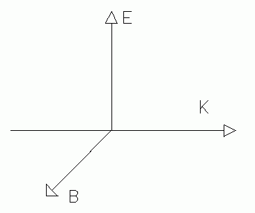 |
| Fig. 1. Electromagnetic model of light. |
|---|
Classical electromagnetic theory provides a model of light which is adequate to describe many phenomena of polarization. This model pictures light as an electromagnetic wave in which the electric and magnetic fields have oscillatory variation. At any point and time the electric and magnetic field vectors are mutually perpendicular, and at any point the electric and magnetic vectors' size maintain the same proportion as time goes on. Because of this strict proportionality between the electric and magnetic vectors, only one vector is needed to describe the phenomena. When discussing light we generally concentrate on the electric vector only, especially since it is the electric field which is the one acting on light detectors, including the human eye. So we use the electric vector to "represent" the light wave.
Though much of this discussion is essentially "classical" physics, one non-classical, quantum aspect of light must be kept in mind: Light is not emitted in a continuous "stream" but in random "bursts," called photons.
In light sources such as incandescent lamps (which produce "black body" radiation) the photons are emitted with random, uncorrelated polarization. Each individual photon may be thought of as polarized, but over a large sample of photons very many randomly oriented directions of polarization are represented. Such a light source is said to be unpolarized.
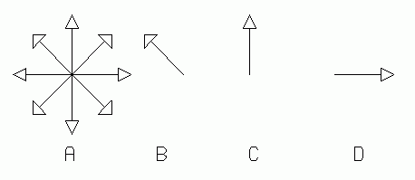 |
| Fig. 2. Conventional symbols for polarized and unpolarized light. A is unpolarized. B, C, and D are polarized along different axes. |
|---|
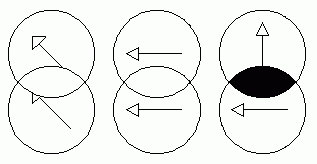 |
| Fig. 3. View through two polarizers at different orientations. |
|---|
Laser light sources emit light which has a number of special properties, including spatial and temporal coherence. Of particular interest here is the fact that lasers can emit photons which all have the same direction of polarization. Such a laser is said to be linearly polarized. Linear (or plane) polarization means that the electric vector of the light has only one fixed direction in space; that direction is called the direction of polarization of the light.
Polarized light may also be produced from ordinary light: (1) by reflection, and (2) by transmission through certain optically non-isotropic materials.
Light incident on the surface of a transparent material is partly reflected and partly refracted. The reflected and refracted beams are partially polarized at most angles of incidence, but at one special angle, called Brewster's angle (1), the reflected beam is completely polarized with its electric vector parallel to the reflecting surface.
Some natural crystals, such as tourmaline, sulfate of ido-quinine, and some man-made plastic materials, have the property of "converting" ordinary light into fully or partially polarized light. They do this by a process of absorption and emission of photons, the emitted photons being forced into certain polarization states by the geometric arrangement of atoms or molecules of the material. In the process, more than 50% of the light energy is absorbed, and the rest is emitted. Polaroid ™, a brand of plastic polarizing material, has this property, and is an inexpensive device for producing polarized light from an unpolarized source. It is also useful for detecting polarization and for determining the direction of polarization.
Circularly polarized light may be thought of as having its electric vector rotating with constant amplitude at a constant angular velocity around its propagation axis. If this model is viewed head on the electric vector appears to be rotating at constant angular velocity, its head tracing out a circle. (2)
Elliptically polarized light has the same character, except that the amplitude also varies, and the head of the electric vector would trace out an ellipse when seen head on.
Some materials have two indices of refraction, and are therefore called birefringent or doubly refracting. Calcite, quartz and mica are examples. The light velocity in such materials depends on the direction of propagation and on the polarization direction of the light, both measured with respect to the crystal structure. A light beam entering such a material is effectively resolved into two components, polarized at right angles to each other. These two components will, in general, travel at different speeds, and also may take different paths through the material. One of these components will obey Snell's law of refraction (3), and it is called the ordinary ray, O. The other one does not obey Snell's law, and is called the extraordinary ray, E. The extraordinary ray does, indeed, seem to do some extraordinary things, for example, it can be refracted even when entering a crystal face at normal incidence, as illustrated in Fig. 4.
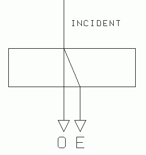 |
| Fig. 4. Double refraction. An incident ray splits into an ordinary (O) and an extraordinary (E) ray. |
|---|
At some angles of incidence (4), the ordinary and extraordinary ray take the same path through a doubly refracting material, but their speeds may still differ. After passing through a thickness of the material they are no longer in phase. Suppose we let linearly polarized light enter such a crystal in this way, with its electric vector oriented so that the ordinary and extraordinary rays in the material have about equal intensity. The progressive shift in their phase is equivalent to a progressive change from linear to elliptical polarization (and even back to linear, if the material is thick enough). After passage through a certain thickness of the material, the light emerges either linearly or elliptically polarized.
A vector model of this effect is shown in Fig. 5. On entering the crystal, the polarized incident ray is effectively resolved into components parallel and perpendicular to the crystal axis, x and y. These two components have different speeds, and have a phase difference upon emergence from the crystal. For a given thickness of crystal there are some wavelengths for which the phase difference is exactly one half wavelength. This causes a 180° shift in one component (relative to the other). Now the light is circularly polarized. Passage through the second polarizer will resolve the vectors into components along the polarizer's axis, and these will destructively interfere with each other. Figure 5 shows this case.
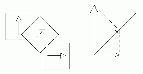 |
| Fig 5. Three polarizers, and the vector method for finding the intensity of the emergent light. |
|---|
If elliptically polarized light passes through a linear polarizer, the polarizer "extracts" a component of the electric vector, and linearly polarized light emerges from it.
In the above discussion we implicitly assumed monochromatic light. Now consider what happens if linearly polarized white light passes through such a crystal. The white light has a continuous distribution of wavelengths. After passing through a given thickness of the material, some wavelengths emerge with their O and E components exactly out of phase. This corresponds to elliptically polarized light. Some other wavelengths may come out with O and E components exactly in phase. This corresponds to linearly polarized light. This light may be allowed to pass through a second linear polarizer. If the second polarizer has its polarization axis oriented at right angles to those wavelengths which emerged from the first polarizer linearly polarized, those wavelengths will be blocked, but the others will get through. The light which emerges will now no longer be white, because certain colors (wavelengths) have been removed. This is how colors are produced when birefringent materials are viewed between two linear polarizers. (See Fig. 5 for the theory and Fig. 6 for the experimental arrangement.)
A piece of polarizing material may be used as a polarizer, or as an analyzer. A Polarizer is used to produce a polarized beam from an unpolarized one. An analyzer is used to detect whether light is polarized, and if so, determine the character of the polarization (linear or circular) and its direction (if linear) or sense of rotation (if circular).
5. QUALITATIVE OBSERVATIONS OF POLARIZATION
Even if you have seen some of these demonstrations in class, you are advised not to skip them, but make sure you can reproduce the phenomena. As you do this you may also make some new discoveries.
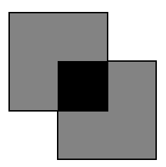
(1) Use one polarizing sheet as a polarizer and the other as an analyzer. Observe the change in transmitted light intensity as either of the sheets is rotated. This combination acts as a "light valve." [See section 8, (3) for quantitative study of this.]
(2) Light reflected from smooth surfaces is polarized. Look through a single polarizing sheet at the light reflected from a shiny floor, smooth table top, or sheet of glass. Use a table lamp as a source of light and try different angles of incidence. From electromagnetic theory we know that the light reflected from a smooth surface has a predominant polarization orientation which lies parallel to the surface. Draw a picture of this, and use this fact to determine the polarization axis of the polarizing sheets you are using.
Notice that the polarization is greatest (most complete) at a particular angle of incidence, called "Brewster's angle." This angle depends on the material of the reflecting surface. Estimate it for the reflecting surfaces available. You can use a spectrometer to look at light reflected from a glass surface to accurately determine Brewster's angle. [See section 8, (1) for quantitative study of this.]
(3) Sky light is polarized, but to observe this you must be careful.
Do not look at the sun directly, and especially do not look at the sun through an optical instrument such as a telescope or binoculars.
Do not look at the sun through crossed polarizing sheets either. Crossed polarizers (5) do not effectively absorb the ultraviolet light or infrared light, both of which can permanently damage your vision.
Face a patch of blue sky located about 90° from the sun. Look at this part of the sky through a single polarizer, and rotate the polarizer to check the direction of the sky's polarization. Which parts of the sky are polarized most? Where are they, in relation to the sun? What is the direction of polarization relative to the location of the sun? [Consider an imaginary plane which includes your line of sight and the sun. This is the plan in which the light travels before and after it is scattered. Is the scattered light's direction of polarization in this plane, or perpendicular to it?]
6. OBSERVATIONS OF DOUBLY REFRACTING MATERIALS
All of these phenomena may be projected onto a white screen by placing a specimen of material between polarizers on an optical bench, with "projection lantern" illumination (see experiment L-3). This arrangement is called a "projection polariscope." A commercial polariscope may also be used for larger specimens, or one may be constructed from a light box with frosted glass. For very small specimens a polarizing microscope may be made by putting a polarizer in the light from the substage illuminator, and another just above the ocular. The latter may be easily rotated.
(1) Observe the double refraction of calcite. Place the calcite crystal over a small dot on a piece of paper and observe the double image of the dot seen through the crystal. If you look straight down at the paper, one dot image seems to be in it's "normal" place, the other seems displaced sideways. [Rotate the crystal to confirm this.] These two images result from the "ordinary" and "extraordinary" rays (components) of the light passing through the crystal.
The calcite can be mounted over a small hole in an opaque card, and placed in the projection polariscope. You will see two images of the hole on the screen. Check the polarization of each image. Rotate the crystal, and identify which is the extraordinary ray.
(2) Some crystal specimens are available "sandwiched" between glass plates for protection. When these are placed between polarizers they will appear brilliantly colored. Try this with the two polarizers' axes parallel to each other, and also with them perpendicular to each other. Notice that when one polaroid is rotated 90° the colors change to the complementary colors. What happens when the axes of the polaroids are at 45° to each other? Where did the colors go? Specific materials to try: Mica sheets. Quartz (yellow light will be rotated 90°).
(3) Put a clear plastic material between crossed polarizers. [A plastic comb or ruler works well.] These colors are from "strains" "frozen into" the plastic during the molding and curing process. [Not all plastic materials show this.]
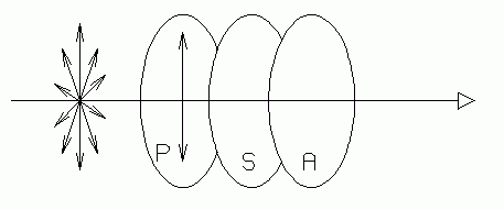 |
| Fig. 6. Polariscope: Two polarizers (polarizer P and analyzer A) with the specimen S between them. |
|---|
(4) If glass is annealed too quickly it can have similar "frozen" strains. Some specimens of "Prince Rupert's drops" and "Bologna bottles" are available which exhibit this. These are manufactured by rapidly cooling (quenching) the hot glass. [The hot glass is plunged into a cool liquid.] If done "properly" this gives added strength to glass by forming a "skin" layer which is under tensile stress. The Bologna bottle can be used to drive small nails, but if merely scratched inside, it shatters. Prince Rupert's drops are made by dropping hot glass in cold liquid. The large part of the drop resists hammer blows, but if the slender tail is broken off, the entire drop shatters. Do not attempt the shattering experiments, your instructor will demonstrate them.
Some "safety" glass for car windshields and glass doors is made this way. When it breaks it shatters into many small pieces rather than large shards with sharp knife-like edges. [Do not confuse this with another type of "safety" glass which is a sandwich of a plastic layer between two sheets of glass.]
(5) Look at the rear windows of automobiles through a polarizer. Also look at plate glass doors if there are any nearby. These are probably the laminated type of safety glass, the glass and/or plastic sheets being strained by the pressure of the laminating process.
(6) Look at fingernail clippings between polarizers. Do this with a polarizing microscope. [Put two polarizers in the light path of the microscope, with the specimen between them.]
 |
 |
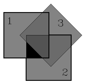 |
| Parallel axes. | Crossed axes. | Polarizer (3) between two crossed polarizers (1) and (2). |
|---|
(7) Obtain three polarizing sheets. Arrange two with axes at right angles for extinction of the light. Now predict what will be observed if a third polarizer is slipped between them, with its axis at 45° to theirs. Try it, and see if your prediction was correct. Try other angles. Try to develop a working model of what is happening.
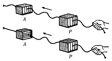 |
| Fig. 7. The "picket fence analogy of polarization. A bad example. |
|---|
Note: Many books "explain" polarization by a "picket fence" analogy. Fig. 7 is from such a book. Waves set up in a rope passing between the slats of a picket fence can vibrate only in a plane parallel to the slats. If the rope passes through two picket sections, with slats at right angles, now waves in the rope can pass through both. As with most analogies, this one is misleading and inadequate. If you imagined a third fence with slats at 45° you would have predicted the wrong result. This simple experiment has shown how this much used (actually abused) analogy is imperfect, and really doesn't "explain" polarization at all. Prospective teachers, take note!
(8) Look at sheets of cellophane between polarizers. At certain angles you'll see colors. [Cellophane tape may be used, stuck onto a plain glass plate.]
(9) Law of Malus. (6) The intensity of light passing through two polarizers depends on the angle θ between the polarizers' axes:
| [Law of Malus] |
Apparatus is available which allows measurement of the angular position of one polarizer. A photocell or other light detector may be used to measure the light intensity emerging from the analyzer, to experimentally verify this law. This is best done on an optical bench in a fully darkened room. Take care to avoid errors due to scattered light from nearby walls.
(10) Optical rotation. Some materials have the effect of rotating the plane of polarization of light, the amount of rotation being proportional to the path length through the material. Sugar solutions (or dextrose), and turpentine, are common examples. The amount of rotation will also depend on the concentration of the solution. The sense of rotation, as seen along the beam, also depends on the material. It may be to the right (clockwise) or to the left (counterclockwise).
Sugar solutions are interesting because some produce clockwise rotation, while others, with the same chemical formula, produce counterclockwise rotation. The difference is in the fact that the molecules of the two kinds are mirror images of each other. It is interesting also to note that some bacteria are so specialized that they will only eat one kind of the sugar, and will die of starvation in a solution of the other kind.
You may observe a small rotation in a deep beaker or tube of solution.
The specific rotation (ratio of rotation angle to length of path) provides a means for measuring solution concentrations. Those students with an interest in chemistry may wish to check this with a solution of known concentration.
7. QUESTIONS
(1) Explain the observations of section 6, part 7, in particular, show how the "picket fence" analogy is wrong and misleading, and how the vector model does give correct results. Use diagrams.
(2) Some books suggest that polarization of light represents strong evidence for the wave theory of light (as opposed to a strictly particle theory). To challenge this glib assertion, devise a particle theory (no waves allowed!) which would be adequate to explain the experimental phenomena studied in this experiment. Be creative, but be sure that your model meets the criteria of good physics:
a) The model must correctly describe known physical facts.
c) The model must be quantitative.
b) The model must be testable and potentially refutable by experimental test.
c) All features of the model must have a clear and precise relation to observables (it must not include any features unrelated to observables).
Do not be prejudiced or limited by any models of light you have already learned.
Even if you are not successful, carry this far enough to show why it would be very difficult to devise such a model.
Text and drawings, © 1995, 2004 by Donald E. Simanek
1. Brewster, Sir David (1781-1868). It is given by tanqB = n'/n. Brewster's angle for glass is 56°.
2. Of course we are speaking of "seeing" the vector model of light. The electric vectors are a mathematical construct, not something "real" one can see with the eye.
3. Snell, Willibrord (1591-1626).
4. The optical axis of the crystal is that unique direction in which the ordinary and extraordinary ray paths are coincident.
5. Polarizing sheets are often called "polarizers" whether they are being used as polarizers or as analyzers.
6. Malus, Etienne Louis (1775-1812).