L-5 TELESCOPES
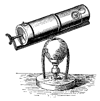 |
| Newton's reflecting telescope. |
|---|
1. APPARATUS:
1 or 2 meter optical bench.
Illuminated object-box.
Object-image device for measuring f of positive lenses.
Screen, for locating real images.
Reference pointer, for locating virtual images.
Long focal length objective lens, f > 60 cm, diameter 50mm or more.
Converging lens for astronomical telescope eyelens, f = 20 cm.
Diverging lens for Galilean telescope eyelenses, f = -20 cm.
Assorted simple lenses.
Wide focusing range telescope and holder, for locating images.
Meter stick to use as object for telescope.
Ramsden eyepiece, or other achromatic eyelens (optional).
2. THEORY:
Study the following topics in any physics textbook: astronomical (inverting) telescope, Galilean (non-inverting) telescope, calculation of telescope magnification. You may also find material on erecting lenses and on Barlow lenses. If so, read about them, but if not, there should be sufficient explanation within the experiment text below.
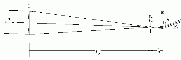 |
| Fig. 1. Ray paths in an astronomical telescope. |
|---|
Fig. 1 shows a ray diagram of an astronomical telescope. The focal points of the objective lens (O) and the eyelens (E) are coincident (Fo and Fe). Parallel rays from a very distant object (infinite p) enter, making angle α with the optic axis. A real image is formed at I. Rays emerge from the eyelens making angle β with the optic axis. The angular magnification is tan(β)/tan(α).
3. PROCEDURE:
Note: Use the object-image screen, or other direct method, to measure the focal lengths of all lenses you use in this experiment.
(1) ASTRONOMICAL (INVERTING) TELESCOPE: Use the larger diameter, longer focal length objective lens and a short focal length positive eyelens to construct a telescope on the optical bench. Choose lenses which give the greatest magnification possible with the length limitations of your bench, leaving about 40 cm of bench length available for later modifications.
(2) Set up a two-meter-stick against a far wall; direct the light from a desk lamp upon it for greater visibility. Observe the meter stick image through the telescope. Use the method of parallax (Exp. L-2). Eliminate parallax between the image of the meter stick, and the meter stick viewed directly. This may be difficult to do with one eye. If so, use both eyes, and move the head up-and-down while looking for parallax shift. Fig. 3 shows approximately what you should see during this process. Record the lens positions accurately, and measure the distance from objective lens to meter stick.
(3) MAGNIFICATION. The magnification of the image is found by directly comparing the size of the meter stick markings as seen through the telescope with their size seen directly. Fig. 2(b) shows a magnification of 2(a). Any telescope may be checked in this way by observing a brick wall and counting bricks over matching lengths of object and image.
 |
| Fig. 2. Magnification determined from direct comparison of object and image of a brick wall. Be sure that parallax is eliminated between the object and image. |
|---|
(a) Object, direct(b) Image, seen through telescope. view with unaided eye.Magnification = 4.
Sometimes this is difficult to do because you can't easily read the meter stick markings at that great a distance. Several remedies are possible.
(a) Tape 10 cm lengths of colored paper along every other decimeter of the stick. This makes them easy to see from a distance.
(b) Have a lab partner go to the meter stick and move an easily visible pointer against it. The observer looking through the telescope reads the position of the pointer relative to the meter stick image seen through the telescope. The person holding the pointer records the pointer position on the real meter stick. This is done for two positions, the four numbers so obtained being sufficient to calculate the magnification. Show how. You must eliminate parallax before doing this, or you will get false results.
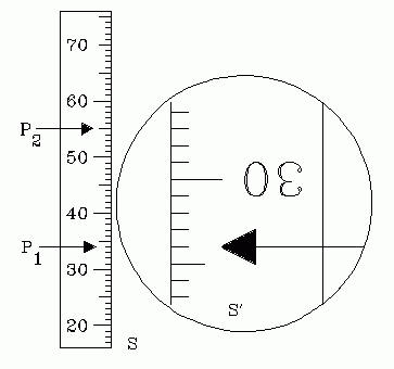 |
| Fig. 3. Telescope magnification by direct comparison. The magnification shown is 3. |
|---|
A pointer P1 is placed on the distant meter stick. In Fig. 3 it is placed at 34 cm and lines up with the image of 34 cm. Then it is moved to position P2, where it is at 55 cm and lines up with 27 cm on the image. The magnification is therefore (55-34)/(34-27) = 21/7 = 3. [It is not necessary that the first reading happened to have matching values for the object and image.]
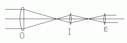 |
| Fig. 4. Erecting (inverting lens in an astronomical telescope. |
|---|
(4) ERECTING (INVERTING) LENS. The image produced by a telescope may be inverted by placing a positive lens between the objective and the eyelens. When this is done with the astronomical telescope, the normally inverted image is made erect again. Fig. 4 shows the case where the inverting lens, I, inverts the image without changing the telescope's magnification much. It adds a length of at least 4fo to the length of a telescope, where fo is the focal length of the inverting lens. [Derive this result.] Construct such a system and verify these assertions. Observe the worsening of image quality which results from use of so many simple, uncorrected lenses. Estimate the usable angle of view of the reasonably sharp portion of the image.
 |
| Fig. 5. Barlow lens in an astronomical telescope |
|---|
(5) BARLOW LENS. A Barlow lens is a negative lens placed in the telescope between the objective and its focal point. Its strength is chosen so that in combination with the objective, the two produce a real image, but this image is farther from the objective than before.
This combination of objective lens and Barlow lens is equivalent to an objective lens of longer focal length. This increases the telescope's magnification. Work out the formula to predict the angular magnification of such a system.
(6) THE TELESCOPE AS A SCIENTIFIC TOOL: [Instructor's option.] The telescope is an integral part of many scientific measuring instruments (transits, spectrometers, etc.). These are usually inverting telescopes. To facilitate accurate image location, they have markings in the image plane of the objective lens. These markings may be simply cross-wires or hairs defining a point, or an engraved scale (reticle) for measuring image sizes. In either case, it is essential that parallax be eliminated between the image and these markings. This is done in the usual way, by moving the eye very slightly back and forth while eliminated. When this is accomplished, the cross-hairs or reticle lie in the image plane, and the measurements of position are not affected by where the observer places his eye. Also, as long as the cross-hair is not moved, the observer may focus the eyelens back and forth to achieve most comfortable viewing, and this does not introduce error into the measurement.
Practice these procedures with the wide-focusing range telescope.
The telescope may be used to locate virtual images. Set up a lens system producing a virtual image, as you did in exp. L-1. Now use the telescope to look back into the system at that image. These telescopes focus as close as about 30 cm. Adjust the cross-hairs to eliminate parallax. Now remove the lens system and object box, being careful not to disturb or change the telescope setting during the rest of this procedure. Move a reference target along the bench while looking into the telescope, until its image has no parallax with the cross hairs. Now this reference object is at the same place the virtual image was before, and you have located it quite precisely. Use this method to measure the focal length of a lens (preferably one you used in L-1) to verify that you are doing this correctly.
(7) GALILEAN TELESCOPE. Repeat steps (1) through (4) with a negative eyelens.
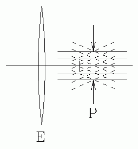 |
| Fig. 6. Rays through an exit pupil. |
|---|
(8) EXIT PUPIL. Set up the astronomical telescope, and focus it on a distant object seen through the window. Place a screen or white paper where the light emerges from the eyelens, and move the screen back and forth until you observe the smallest size bright circle on the screen. You will not see detail in the circle, but its edges will be relatively sharp.
This circle is actually the image of the objective lens. You can verify that this is so by placing your finger, or a pencil point at the objective lens to see if it also produces an image on the screen. This circle is called the exit pupil of the telescope, and it has the property that all of the light entering the objective lens passes through this circle. Ideally, for greatest light efficiency, the observer's own eye pupil should be placed at that position, so it receives all of the light. The designer of the telescope should ensure that the exit pupil size is smaller than the observer's eye pupil size, and that it is far enough from the eyelens housing so the eye can be placed there without the eyelash hitting the eyelens or housing. The distance of the exit pupil from the eyelens is called the eye-relief.
Verify by measurement that the exit pupil is located at the position where the eyelens forms an image of the objective lens. From magnification considerations, verify that the size of the exit pupil is what theory predicts.
4. QUESTIONS:
(1) A positive inverting lens adds a length of 4fo or more to the length of an astronomical telescope, where fo is the focal length of the inverting lens. Derive this result.
(2) On a single diagram like that of question 6, draw rays from infinitely distant points on-axis, off-axis above the axis, and off-axis below the axis. For each angle, draw three rays: one through the center of the objective lens and two which enter at extreme opposite edges of the objective lens. Show that the emergent bundles from the eyelens, E, all pass through the exit pupil, P, as shown in Fig. 6, and find the location of that exit pupil relative to the lenses.
(3) What do you see when you look "backwards" through a telescope? Discuss.
(4) Why might a bird-watcher prefer a telescope or binoculars having larger diameter objective lenses? Why might this also be important in military binoculars?
(5) Where can you place cross-hairs or reticle in a Galilean telescope so that they are superimposed upon the scene being viewed?
(6) Binoculars consist of two telescopes, one for each eye. They are commonly designated with a number, such as 7X50. This means a power of 7X and objective lens diameter 50 mm. What would be the angular field of view (in degrees) of such a binocular if its optical length (objective to eyelens) were 30 cm, and the eyelens diameter is 1 cm? What is the location and size of the exit pupil? Is this a good design? Assume "simple" lenses, and do a ray tracing diagram to help you answer these questions.
(7) An astronomical (inverting) telescope may be converted to a terrestrial (non-inverting) one by adding a converging lens between the objective and the eyelens. This requires increasing the total length of the telescope. Indicate, with a ray diagram, how this can be done.
(8) Use the mathematical theory of these telescopes to predict how the light efficiency of a Galilean telescope compares with that of an astronomical telescope of the same power and the same objective lens diameter.
(9) Figs. 3 and 4 show rays from an infinitely distant object located on the optical axis. Rays from an infinitely distant object off of the optical axis enter the objective lens at angle α to the axis, as shown in Fig. 5.
Complete the construction of these rays through the astronomical telescope. Do this on a larger scale drawing. These rays emerge as a parallel bundle from the ocular. The emergent bundle is inclined to the axis by some angle β, different from the entrance angle, α. Since in this situation all images are at infinity, image sizes are not accessible to measure. That is why the telescope magnification is expressed as angular magnification, defined by m = tan(β)/tan(α).
(10) The angular magnification of any optical instrument is defined by:
M = θi/θo
Where:
θi is the angle subtended by the image, as seen through the optical instrument.
θo is the angle subtended by the object, as seen without the optical instrument, by the unaided eye.
Show that the angular magnification equals fo/fe for both kinds of telescope.
(11) The theoretical magnifying power of a telescope (fo/fe) is correct only when both object and image are at infinity. The situations you have investigated do not satisfy these conditions. Derive the correct magnifying power formula for the case where the object is a finite, but large, distance away and the image is at infinity. Compare your results with the predictions of this formula. Hint: let the object be distance p away, where p << fo.
(12) The magnification of a telescope may be increased by adding a diverging lens between the objective and the eyelens. Astronomers call such a lens a "Barlow" lens. This requires increasing the total length of the telescope.
The same "trick" is used in photography to increase the effective focal length of a camera lens. The negative lens adapter is put between the camera body and the camera lens. Such devices are sold under the name "telextender" and are particularly useful for portraiture, and close-up photography of small objects at longer working distances.
The combination of objective lens and Barlow lens is equivalent to an objective lens of longer focal length. This increases the telescope's magnification. Work out the formula to predict the angular magnification of such a system.
Text and line drawings © 1994, 2004 by Donald E. Simanek.