E-6 TEMPERATURE-DEPENDENT RESISTORS
1. PURPOSE:
To use a commercial Wheatstone bridge to measure the temperature coefficient of resistance of a copper wire coil and of a thermistor.
2. APPARATUS:
-
Commercial wheatstone bridge.
Precision galvanometer.
1.5 v power source.
Temperature coefficient apparatus, copper coil, thermistor.
Thermistors, for direct ohmmeter measurement.
3. THEORY:
See experiment E-4, Slidewire Wheatstone Bridge, or any textbook. The circuit for the Wheatstone Bridge is shown in Fig. 1.
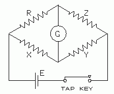 |
| Fig. 1. The Wheatstone Bridge Circuit. |
|---|
By application of the circuit laws, it can be shown that when the bridge is balanced, the unknown resistance R is given by
R = Z(X/Y)
4. APPARATUS
Commercial bridge. The commercial bridge is contained in a relatively small box, with all necessary components (except for the power source) built-in. It may contain a slidewire, wrapped on a drum with a calibrated dial. Or it may have a set of resistance coils selected by a "range selector" which sets a ratio of X/Y which becomes the "multiplier" for the value dialed on the resistance box. The precision resistance box is also built into the same box or case. This form of the bridge allows for faster balancing. Typical commercial bridges have a guaranteed precision of 1% for the resistance dials, and 0.05% for the range selector (ratio) dial.
Even the necessary switches are built into this bridge. One push button, labeled BA, represents the switch in the battery circuit. The other, labeled GA, represents the switch in the galvanometer circuit. These are momentary contact switches, but may also be locked in the on position by pushing them down, then gently rotating them 1/2 turn.
Normally the battery button is closed only while actually balancing the bridge or taking readings, especially when measuring low resistances.
Use only 1.5 volts to power this bridge The power source need not be well regulated.
5. SOURCES OF ERROR IN WHEATSTONE BRIDGE MEASUREMENTS:
Read sections (5) and (6) of experiment E-4. One error source unique to the slidewire bridge will not be of concern here. A well designed commercial bridge has roughly the same precision at any setting of the ratio switch, so there is no need to keep the ratio X/Y near one.
In this experiment you will use a meter sufficiently precise that it will probably not be the dominant source of error.
One could go back to first principles and re-derive the bridge equation for the case of a slightly unbalanced bridge, to see how much unbalance is required to make the galvanometer current large enough for an observable deflection. This is messy. The derivation may be found in various reference books. An experimental study of the errors is usually sufficient, in the spirit of that described in experiment 4.
The full derivation may be found in (1) Stout, Melville B. Basic Electrical Measurements, 2nd Ed. Prentice-Hall, 1960. (2) Brophy, James L. Basic Electronics for Scientists, 5th Ed. McGraw-Hill, 1990. It's also in earlier editions of these books.
6. MEASUREMENT PROCEDURE:
Preliminary qualitative observations.Some small thermistors are available in lab that can be connected diretly to an ohmmeter. Do this and observe the effect of warming the thermistor between your fingers, or dipping your fingers in ice water. The thermistor may also be heated gently with a match or hot soldering iron (near it, not touching it).
Most resistors are temperature sensitive. You will use a special apparatus to measure this temperature dependence. The resistive elements are immersed in a water bath which is heated by an electrical heater. The heater has a switch in its line cord which can be closed at intervals long enough to cause the temperature to rise a few degrees at a time. Begin with cold water (from the water-cooler in the hall, or cool some water with ice).
You will measure a resistance which continuously changes its value with time. By the time you get the bridge dials set, the resistance may have changed considerably. To avoid this frustration, the measuring procedure may be done in the following manner. Determine the direction in which the resistance changes as the temperature rises. Balance the bridge dials so that the galvanometer needle is off-zero, but moving toward zero. Then when the needle hits zero, simultaneously read the temperature and the resistance dial settings. Then reset the bridge dials so the galvanometer is again off-zero as before and wait for it to reach zero again.
Two kinds of resistors are available for this apparatus. One is a length of copper wire wrapped on a cylinder. The other is a solid state device called a thermistor. Take data on the thermistor, and, if there is time, also on the copper wire.
7. ANALYSIS:
Thermistors are solid state devices which have very high coefficients of resistance, and also display a non-linear relation between R and T. They are non-ohmic. They are useful as stabilizing devices in transistor circuitry, to counterbalance a similar temperature dependence of transistors. Thermistors are also used as temperature sensi- tive transducers in electronic thermometers. The temperature sensitive resistor you used in section 7, step (3) is just a thermistor.
A transducer is a device that converts the measurement of one quantity, say temperature, into the measurement of a related quantity, say potential.
We have deliberately not revealed what mathematical form of equations the various temperature sensitive devices obey. It depends on the device. You will find out, from your data, what the equations are.
The resistance of many materials is approximately linearly related to their temperature by
| [2] |
R = Ro (1 + αT)
where Ro is the resistance at 0° C and α is the temperature coefficient of resistance. If the graph of resistance vs. temperature is linear, use this equation to calculate α.
The resistance of some materials is non-linearly related to the temperature. The resistance vs. temperature graph will be obviously curved.
The relation might be an exponential dependence on temperature:
| [3] |
R = k eβT
which can be converted to an equation of the form:
| [4] |
ln R = ln k + βT
| [5] |
or: log R = log k + βT log e = log k + T(b log e)
The equation graphs as a straight line with slope T on semi-logarithmic paper. Plot R on the log scale, T on the linear scale. [Or graph log R against T on linear paper.]
Or, the relation might be described by a power law:
| [6] |
R = A Tn
where T is absolute temperature, and A and n are constants. Such curves may be "straightened" by plotting the data on log-log graph paper, which automatically converts the graph to the form:
| [7] |
log R = log A + n log T
where n will be the slope of the line, which may be easily found from two widely separated points on the line.
The constants A and n can be determined from this graph. When log T = 0, then log R = log A. This determines A. The exponent n is obtained from the slope of the curve. Take two points on the curve, and widely spaced. Call these points 1 and 2. The slope, n, is then:
| [8] |
      log R1  - log R2
n = ———————————————————
      log T1  - log T2
If the cycle length is the same on both axes of your graph paper, the slope may be taken in the usual way, i.e. by measuring lengths of the legs of a triangle with the straight line as a hypotenuse.
Do this analysis on the data from the thermistor and determine which kind of equation best fits your data. If you need to plot T or R on the log axis of log paper, note that the data on temperature spans only one factor of 10, so only one cycle will be required. The resistance data, however, spans two cycles.
But most authorities prefer to give the relation for a thermistor in this form:
| [9] |
       β(1/T - 1/Ta)
R = Rae
where Ra is the resistance at temperature Ta (a reference temperature, near room temperature). Ta may be one of the temperatures in your data set. All temperatures are in degrees Kelvin.
To analyze this relation, take the natural logarithm of both sides.
| [10] |
ln (R/Ra) = β(1/T - 1/Ta)
This may be graphed on linear paper, or one can use common (base 10) logarithms:
| [11] |
log (R/Ra) = β(1/T - 1/Ta)(log e)
Semi-log paper may be used to graph ln (R/Ra) vs. (1/T - 1/Ta). The slope should be β(log e).
© 1995, 2004 by Donald E. Simanek.