Fooling around with pulleys.
By Donald E. Simanek.
[1,611 words]MAKE magazine readers like to make things, and hope that what they make will work as they intend them to. That doesn't always happen.
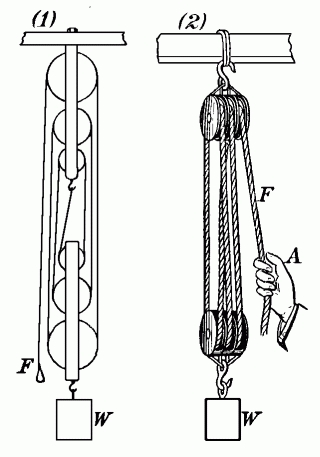 |
| Fig. 1. Block and tackle. |
|---|
Rope and pulley systems, such as the "block and tackle", have been useful since earliest times. They were among the "simple machines" described by Archimedes, and are among the first useful mechanical systems studied in introductory physics courses. High school physics students in my day knew the block and tackle system of Fig. 1, and knew that its ideal mechanical advantage was equal to the number of rope segments supporting the load, six in this case. (The leftmost segment doesn't support the load.) Its ideal mechanical advantage is equal to the ratio of the distance the applied force moves compared to the distance the load moves, assuming the rope doesn't stretch. The ideal(ized) mechanical advantage is also an upper limit on work performance, assuming that there's no friction and that the weight of any pulleys that move up or down is negligible, i.e. the idealized system is a perfectly efficient machine with no mechanical energy losses. Real systems come nowhere near this ideal, and the ratio of their load to applied force is always less than one. Efficiencies of pulley systems can range from less than 50% to over 90%, but 80% is typical.
There's a problem with this sort of "crammed knowledge". If the student is confronted with a pulley system that is not a block and tackle, the "number of ropes suspending the load" rule is out the window.
In physics ed-biz circles many of us know of the "Fool's Tackle" deception, shown in Fig. 2. There isn't much about it on the internet, and it seldom appears in textbooks, so I assume it is not generally known. It looks good on paper, and the naive student will conclude that its mechanical advantage is 2.
 |
 |
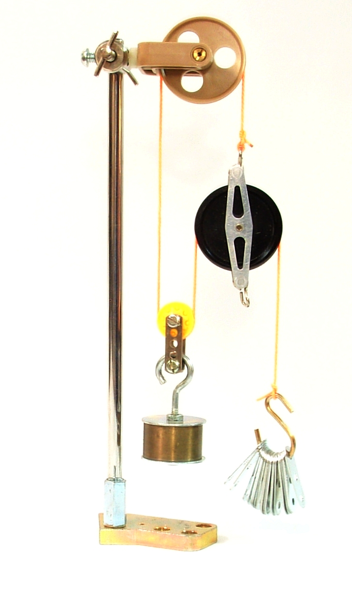
| Fig. 2. Classic fool's tackle. | |
|---|---|
Here's the trouble. You can't construct it. Any attempt to build it (honestly) causes its collapse. Of course, you can use deception to make constructions that appear to be fool's tackles, and can even make ones that seem to "work". You can also draw an inverted version of it that doesn't work either, as in Fig. 3. Combining an impossible device with other mechanical devices, either workable or unworkable ones, is not productive either. There's a lesson in that. A plausible-looking drawing can often deceive. I see a lot of that in email stimulated by my "Unworkable Devices" web pages. I also see it in the patent literature.
This device goes a long way back. Sailors in the days when ships had sails were expected to understand ropes, knots and pulleys, and be able to construct and use pulley systems. Newbie sailors were given some rope and pulleys and assigned tasks to test their skills. Sometimes this included the task of building and using one of these fool's tackles, partly as a joke, partly to see how savvy they were about machines. We physics profs would do the same with students in elementary physics courses. And most students fell for it, some even spending half an hour trying to build the system before asking for help. I'd usually respond to these plaintive requests by saying "Didn't we tell you to do a pencil and paper analysis of the system's performance before building it?" There were even some who reported fake data and analysis hoping it wouldn't be noticed.
 |
| Fig. 3. Inverted fool's tackle. |
|---|
Some things that you can describe in words are simply not possible in nature. For example, a four-sided triangle, or a string with only one end. But these are semantic deceptions. Some impossible tasks violate the physics of the real world, such as a walking path that traverses a closed loop to return to its starting point, downhill all the way. How about constructing an equilateral triangle in a flat plane with no two angles equal? Give those tasks to someone who asserts that "anything is possible."
 |
| Fig. 4. Force analysis of the fool's tackle. |
|---|
So how should one analyze a rope and pulley system? In the idealized (and static) case the tension in the entire length of a rope of negligible weight is nearly constant throughout its length. Call that tension T. So the segments of a rope passing over a pulley sheave have the same tension. In the diagram of the fool's tackle, Fig. 4, we see that this tension exerts forces on the pulleys as shown. But the pulley at the right experiences twice the tension acting downward as is acting upward, so that pulley cannot be in equilibrium. That pulley will fall due to the unbalanced forces. The system has an internal contradiction. It's even worse in reality due to the weight of the right hand pulley. The system will collapse if you try to build it.
 |
| Fig. 5. Spanish burton. |
|---|
So now try your skills on this pulley system, Fig. 5, called the "Spanish burton". It is shown in Leonardo da Vinci's notebooks. What's the number of rope segments 'supporting' the load? That's hard to count, for only two forces from one rope act directly on the load. That "count the ropes" rule is useless for anything other than block and tackle systems. But the analysis of this system (or any pulley system) is easy. First assume the system is in equilibrium (either at rest, or with everything moving at constant speeds). Start at the right, calling the tension in the right rope F. This rope passes over the pulley second from the right, exerting an upward force 2F on that pulley. So, to maintain equilibrium, the rope acting downward on that pulley must have tension 2F. At the next pulley the downward force is 4F, and at the next it is 8F, and by the time we get to the last pulley, the downward force must be 32F = L. So the mechanical advantage is 32, and there are nowhere near that many ropes or even rope segments in the system. (There are 5 ropes and 10 segments.)
One thing seldom addressed in textbooks is how to do estimates (back of envelope calculations) comparing efficiency of different systems. Suppose that each pulley, moving or not, had a force due to friction proportional to the weight its axle directly supports. Suppose also that each pulley that moves up and down had a non-negligible weight. Now what could possibly be the superiority of the Spanish burton over a block and tackle with the same ideal mechanical advantage? The block and tackle would have to have 32 pulleys compared to the six of the Spanish burton, and the block and tackle would have 16 pulleys moving, compared to five of the Spanish burton (moving at different speeds, of course). But the Spanish burton has geometric problems, as well as problems with rope stretch. The diagram is misleading, because the pulley spacing, bottom to top, must be 1, 2, 4, 8, ... at all times. This system is seldom seen with more than 2 or 3 movable pulleys. Leonardo took things to extremes, often drawing pictures of things that weren't practical.
I've raised some questions that you can easily answer by building such systems and testing their performance. Small pulleys can be obtained at science-supply stores, or from toy construction sets. Add some stout non-stretchy cord (like mason's cord) and some weights or small spring scales and you can have a lot of fun learning about simple machines. (This is the toys part of this article.) You can also devise puzzles such as "Given N pulleys and N ropes, what's the greatest mechanical advantage you could achieve using all of the pulleys? What's the greatest efficiency you can get from them? No matter how ingenious you are, you probably won't find an unworkable system that doesn't have a fool's tackle hidden within it. (Some mathematician may be able to prove this as a theorem.)
One can buy "simple machines" educational toy kits with the necessary parts. But to get full benefit from them children need to have some guidance and challenge, through questions of the "What if?" kind, along with "How?" questions that stimulate measurement and quantitative analysis.
Notes.
1. The construction of Fig. 2 could be a fool's tackle in the act of collapsing, photographed with high shutter speed. Actually the upper pulley and string were blocked from moving by a wedge of soft foam plastic between the pulley and the frame. (This is a trick.) Could we call this the "blocked tackle"?2. Homework: (This is a teaser.) Draw as many two-dimensional pulley systems as your inventiveness allows. (Two dimensional pulley systems are those where the pulleys can only move up or down and all rope segments are parallel.) Classify them as workable or unworkable. Without doing a force analysis, can you spot the common geometric feature of the unworkable ones? (Failed machine designs are always due to an attempt to violate the geometry of the universe.)
3. Answer: [To be printed upside down.] A movable pulley has three rope segments acting on it, two of them due to a single rope passing over the sheave. The two segments over the sheave exert a net force 2T on the pulley in the same direction, so the third rope segment must have tension 2T in the opposite direction, to achieve force equilibrium. Therefore that third segment cannot be part of the same rope passing over the sheave, for its tension is only T throughout. Conclusion: An idealized pulley system is unworkable if even one movable pulley is acted upon by only one rope.