Analysis of Murilo Luciano's articulated overbalanced chain.
|
There are many distractors in this clever problem. It's tempting to discuss all of them. But we will refrain for now and give you the shortest answers we can.
Note: The guide rails around the chain and along the inside of it supply only "constraint" forces which act on the chain only perpendicular to the chain's intended motion. Threfore they may be neglected from our analysis.
Solution 1: Let the distance between adjacent compressed links be D. Suppose the geometry of the chain is such that the distance between expanded links is 2D If this chain turns very slowly, as shown by the arrows (or is manually turned, if it refuses to turn on its own), we note that as the left side moves down a distance D, the right side links move up by distance 2D. One link going around the lower pulley expands from D to 2D. This expansion of a link requires work. (We are here using the virtual displacement idea, in the spirit of Stevin's principle.)
At the same time, one link going around the upper pulley, unlatches and causes a cascade of events down the left side until a new compressed link appears on the left.
The net result is that nothing has changed. The state of the entire chain is indistinguishable from before. Therefore, Stevin's principle tells us that this displacement will not occur by itself.
Solution 2: Look at what's happening at the lower right portion of the chain, as it emerges from the lower loop. The chain itself is acting as a compound lever system, lifting the right hand portion of the chain more than the left hand portion is lowered. In fact, considered as a lever, this has a mechanical advantage equal to the outer radius of the chain divided by its inner radius. This is the same as saying that the left hand portion of the chain is supported by the cylindrical weights closest to the center of the lower pulley (those that touch each other), while the right hand portion is supported by those weights farthest from the center, held apart by the locking strips.
The neat thing about this deception is the fact that the lever system is "hidden in plain sight" but in an unexpected place—in the chain itself! Many people, even those who have had a physics course, think all levers are "simple levers", and think that the law of the simple lever applies to all levers. That's not so, for compound levers can behave differently.
The laboratory double-pan balance is a well known example of a compound lever. This design has the useful result that it doesn't matter where you place weights on the pan. You can move the weights closer to the fulcrum or farther away without disturbing the balance, so the balance is not determined by the distance of a weight from the fulcrum, as it would be in a simple lever, but only by the weights on the pans. This is an example of a Roberval balance sometimes presented as a physics lecture demonstration to perplex students and to encourage them to look carefully at details of compound lever systems before drawing hasty conclusions.The drawing of Fig. 1 helps to mislead the reader, for it illustrates a balance which is a simple lever. But the actual device in Fig 2. is a compound lever. The juxtaposition of the two drawings suggests they are analogous, but they aren't.
 |
Look at the bottom portion of Murilo's diagram. He has shown one of the links blackened on the left. That's the link that supports the entire weight of the left side of the chain. I have colored a link red on the right. That's the link that supports the entire weight of the right side. Notice that the red link on the right has a greater distance from the center of the bottom pully, compared to the distance of the black link on the left. The red one has a greater lever arm than the black one. By the law of the simple lever, when the product of weight and lever arm on the left equals the product of the weight and lever arm on the right, the system is in equilibrium (balance). This shows how the shorter arm on the left can support more weight of chain than the arm on the right.
Here's an example of how careful analysis can teach us something about how nature works. The unexpected balance condition of this chain results from its geometric construction. All machines' performance is constrained by geometry. Most, maybe all, devices that seem to work "on paper" fail in practice because we neglected geometry. In this device, one might think you could alter the geometry of the chain links to overcome this inconvenient fact, but every attempt will fail.
|
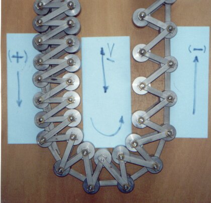
What does happen? Suppose we carefully held everything in place as illustrated in the drawing above. What happens when we "let it go"? Actually, nothing. The system just sits there, unmoving. Sure, there's more weight on the left than the right, but because the effective lever arm on the left is shorter than that on the right, these unequal weights are exactly in balance. It's a neat geometrical exercise to show that the design of the chain causes the ratio of the lever arms to exactly equal the ratio of link spacing of the two sides of the chain, and also exactly equal to the mass ratio of the two sides and therefore also the linear density ratio of the two sides. As so often happens, this PMM proposal is "done in" by the cruel facts of geometry.
So why doesn't Murilo build and test it? The photo (above) which Murlio sent, and gave me permission to use, shows a good portion of the chain. In fact it shows enough already to test his concept. He need only add a support wheel on good bearings at the top and connect the chain segments into a loop. If Murilo's premise has any validity, the additional weight of the links on the left is considerably more than that on the right. Will the chain show even the slightest tendency to turn of its own accord? No. Has Murilo even tried this? I find nothing in all his talk and bluster to indicate that he has ever even assembled it. Why did he go to the trouble to make all those links and weights and then never try it?
If he did try it, I predict it will just sit there, perpetually, in any position of the chain. No doubt he'd have excuses for this: friction, the chain isn't long enough, the links and catches aren't machined quite right, the phase of the moon and alignment of planets wasn't auspicious. We've heard those rationalizations before. He may suppose a larger chain would have a greater "unbalance" on the right. But it also has a greater mass of chain to lift on the left. In fact, if the chain were longer it wouldn't be better, for the friction increases with the load, and a chain twice as long (and twice as heavy) would have twice the friction. The bottom line is that he doesn't need a longer chain to test his assumed (but wrong) principle.
Murilo may sincerely believe that something like this could be made to work. But like so many other perpetual motion promoters he can't be bothered to demonstrate it for all to observe. He just spends his time crowing about his wonderful invention on several internet forums. And what about his cheering section on these forums? Why can't they trouble themselves to build and test something so simple as this?
The bottom line. This puzzle seduces us with a clever idea (latching strips), distracting us from noticing the compound lever in the chain. That chain design, which seems, on casual analysis, to be the feature which should make this PMM work, actually dooms this machine to failure even if the latching strips could be made to perform perfectly reliably.
|
Details
Some readers requested more details of the geometry mentioned above. This drawing may help. The lower part of a schematic chain is shown as it passes over the lower pulley. The details of the chain linkage may take many forms, so we leave out details not essential to the argument. [The fact that our schematic chain does not have the zig-zag appearance of the chain in the photo above is of absolutely no importance to our argument.]
The chain's roller weights are shown in light blue, links in light green, and locking strips in darker green. The lower wheel is grey.
The chain links are collapsed on the left, each supported by the link below. The chain links "fan out" going around the pulley, allowing the locking strip latches to engage. Therefore the links are forced to be farther apart on the right as the move upward. The amount of separation is strictly controlled by geometry. On the left they are separated by distance X and on the right by larger distance Y. Two radius values are important here, the radius A from the center of the pulley to the blue roller on the left, and the radius B from the center of the pulley to the red roller on the right. Observe that the left column of links is supported by an upward force G of the blue roller on the left. The right column of separated links is supported by an upward force of size S of the red roller on the right (acting at the larger radius B).
As the chain turns through an angle, the compressed links on the left side move down a distance X while the expanded links on the right side move up a larger distance Y, because they have a larger radius of motion. For small angles: XA = YB.
Here's a good exercise for the reader—to show that the chain will be in equilibrium of forces when equal length columns of chain are supported on left and right. And, of course, the weight of the left column will be greater than the weight of the right column.
But if the reader is in a hurry for an answer, here's the details:
X/A = Y/B, since both sides move through the same angle.Footnote on Momentum.The weight of chain column on the left is G = mL1/X. On the right it is S = mL2/Y.
The forces G and S support these columns, and their ratio is G/X = (L1/L2)(Y/X).
The two sides of the chain are of equal length. L1 = L2.
That is, 1 = (L1/L2) = GB/SA.
Then G/S = B/A, or GA = BS, which tells us that the torques add to zero, so the chain is in static equilibrium. This will be the case whatever are the values of the radii A and B.
We seldom comment on momentum here since our ground rules are to examine these devices withoutout resort to conservation laws. This is a good example to show how momentum considerations can illuminate certain aspects of the machines' behavior, and also illustrate the limitations of momentum conservation to find out certain details of the machine's behavior.
The geometric constraints force the chain to be expanded on the right and contracted on the left. This would be true even if the chain were moving, perhaps driven by power applied to one of the pulleys.
So if the power were removed, would it continue to move at constant speed (revolutions/second)? Conservation of momentum is satisfied by such an imagined motion. The instantaneous speeds of the two vertical columns of the chain are in inverse proportion to the link spacing of these sides. The mass of the two columns is in inverse proportion to the link spacing also. They are moving in opposite directions. So the vector sum of the momenta of the columns is zero and remains zero at any speed of the device. This momentum does not change over time. (We have ignored momenta at the top and bottom of the chain, of course, but if we took the time to do the math we'd find that also adds to zero.)
But what does this tell us, exactly? It suggests that the net force and the net torque on the device is zero. But momentum conservation alone doesn't rule out the possibility of constant turning of the chain—as a perpetual motion machine of the first kind.
Momentum conservation alone cannot give us a complete picture of the operation of a device. Energy conservation alone cannot either. But with a machine claiming to be a PMM, very often we can learn enough to determine whether it will work from energy conservation alone. Even then, we must resort to a force analysis to determine eactly how the device will behave if it were built, and to determine where it would come to rest under the action of dissipative processes.
An experimental demonstration.
|
No perpetual motion machine is a total failure. It can always be used as an instructive example, or a classroom demonstration to illustrate misconceptions about physics. This PMM's modus non-operandi was a misapplication of the law of the simple lever to a system which was actually a compound lever.
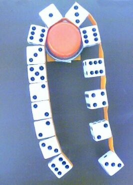
The photo illustrates a demonstration of this mistake as a "paradox" to tease students. It consists of a chain of game dice 1.5 cm on the edge, held together with two strips of limp plastic orange colored tape. The chain hangs over a low friction pulley made from a ball bearing assembly with all lubricant removed, so that it moves very freely. The pulley diameter is 3 cm. [Lubricant in such bearings isn't to reduce friction, but to mimimize wear and conduct heat under heavy loads. The lubricant actually increases friction, compared to a dry bearing.] The cost of materials for this demo was less than $10, so you can easily build one yourself and test it. The ball bearing was the major part of the cost.
If you do this as a classroom demo, first show that the chain is quite flexible. Then put it over the pulley, holding it in place so it cannot move. Now ask the students, "When I release this system, which way will the pulley turn as it falls?" Answer the question yourself, by examining this photo. Most freshman students will say that since the left side is heavier, then the pulley will turn counter-clockwise.
The pulley moves quite easily, and if the system is jostled just a bit, the pulley will rotate, and the chain of dice will move and fall to the floor. But if carefully positioned, it will remain at rest in static equilibrum, as it was when this photo was taken. It is proper to say the two sides "are in balance". But saying this does not mean that the weights are the same on both sides. It only means that both the forces and the torques on each and every part of the system sum to zero.
So, the system is in static equilibrium, with seven dies hanging on one side and only four on the other side. Clearly there's more weight on the left side.
Here's some questions for the physics student.
- If the system is disturbed, which way will the pulley turn as the chain falls? Any answer that depends on the number of dots showing on the die faces is unacceptable.
- How can the weight be larger on the left and the chain still be in static equilibrium? Do a complete force and torque analysis.
- Why do the suspended chains of dice lean toward the right? Of course, the simple answer is that it's because they both are taped together on the right, but we want a more detailed physical answer. No, it's not due to a wind from the left. Also, the camera was not tilted.
- Consider each suspended part of the chain separately, do a force analysis, and show explicitly that the net force and torque on each part is zero.
- From a reader: Ok - I understand that the links on the left will fall due to gravity as they pass over the top and then be squeezed together as they are in the pictures. What I am wondering is if the wheel at the top of this chain isn't a toothed gear, then how are the links at the right able to pull themselves up and apart. If the operation of this chain is gravity based, then there would need to be a toothed gear at the top in order to pull the links up. Please let me know what I am missing.
Return to the top of this page.
Return to the New Aquisitions Gallery.
Return to The Museum of Unworkable Devices
main gallery.