 |
| Installing a new exhibit in the museum. |
|---|
New Acquisitions.
Here's a collection of machines designed by inventors in this 21st century. We plan to keep only those which have some new feature, or new mechanical implementation not previously seen in the long history of invention. Warning! Some of these might be a bit messy to analyze.Two .swf animations on this page may require that you have Adobe Flash player or active-X on your computer. Some browsers don't allow shockwave-flash animations even if you have Adobe Flash installed, and most experts advise that it isn't safe to use. If I knew how to convert these animations to a better system I would. Advice welcome.
Contents
- The Flipping Linkage
- Patrick Voet's Perpetuum Mobile
- Flipping Magnet Motor
- Articulated Overbalanced Chain.
- Buoyant Optimism.
- The Wall Crawler.
- The Power Amplifier Fallacy.
The Flipping Linkage.
I like simple concepts, and this is as simple as they come. It was found in 2017 on a webpage www.sentally.com. It has since disappeared from that site. That happens when perpetual motion machines are allowed to run too fast. The page has a note: "© Images and text published on this site ARE NOT copyright protected"—a very curious disclaimer. A link at the top of that page showed a photograph of a prototype, but I neglected to download it.
 |
Here's how the inventor describes it. I have added text in square brackets for clarity.
Picture visualises the prototype work cycle. Weight of the balance (blue circle) is equal to the weight of both counterbalances (red circles). Also length of brown and blue lines representing levers are equal. Black points in the middle of the circles show their centers of mass. Black points separating brown and blue lines stand for fulcrums (pivoting points).We suspect the inventor used a significant push to supply that "mysterious" force on the blue mass to make it "pass over its equilibrium point".When blue circle in its extreme upper or low position [the system] counter balances also on their extremities but on the opposite side. At this moment entire system is in equilibrium and can freely rotate around horizontal axis.
Now let’s assume that friction is negligible and the blue circle at the bottom. Some "mysterious" force kicked it upwards, as shown on the picture - leverage ratio is not equal anymore. Red circles are lifting the blue one until the system regains its equilibrium but this time blue circle got to the top.
Because of regained equilibrium it does not take much work to flip the system [about the horizontal axis, dotted line] , as well, we do not need induced current to do it. Let the blue circle (aka balance aka moving part of linear generator) gain some momentum and pass over equilibrium point - the system flips on its own. How to do it with minimal losses not in the scope of this page.
Replacing the balance (middle piece) [blue] with a Linear Generator allows gravity-into-electricity conversion ...
Multiple tests run on the prototype have shown that machine does not work if at the positions of equilibrium angle between lever and horizontal (rotation) axis surpasses 30°. The heavier is the machine - the more power it produces, its efficiency varies between 17.3 % and 7.9 % (at 30° and 20° respectively). Efficiency was calculated using Newton-Leibniz formula. Theoretically the highest net efficiency can be reached at 45°.
The Newton-Leibniz formula, sometimes called the fundadmental theorem of calculus, is not a physics principle, and it isn't clear why the inventor invokes it here. Nor is it clear how those efficiencies were determined. He says his prototype device doesn't work with angles greater than 30°, so how can he say that the highest net efficiency is at 45°?
The solution is left as an exercise for the reader.
Patrick Voet's Perpetuum Mobile Machine
Graphic designer Patrick Voet sends us this clever idea that should challenge readers to figure out why it can't work.
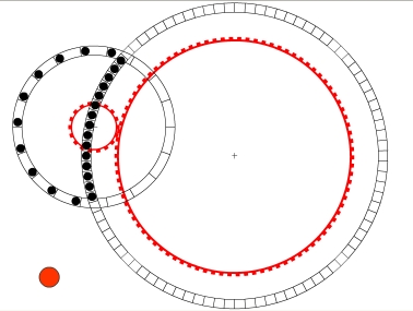 |
Two compartmented wheels are free to rotate on parallel axes, but one is offset so that balls in the compartments can move freely from one wheel to the other. As the animation shows, there are more balls descending on the larger wheel than are ascending on the smaller wheel. The two wheels are synchronized by gears.
Count the balls and gear teeth and measure everything to convince yourself that the geometry is correct. It is.
This ingenious arrangement has elements in common with a number of other devices in this museum, inclulding some rather old ones. We won't tell you which these are just yet.
Flipping magnet motor
Click on the triangle at lower left to see the animation. Click on the square at lower right to view it full screen. This gif animation was converted from an swf file, so the "pause" and "play" buttons do not function.
 |
| André Barata's flipping magnet motor. |
|---|
Computer analyist André Barata sends us this nice animation of a magnet motor. The three rotatable magnets engage the four segments of geared rack. The four circular arcs are guide rails to keep each magnet in position for strongest attraction for a certain time, until it encounters the rack gears, which then rotate the magnet 180°.
Note that the rotor has three rotatable magnets while the outer ring stator has four fixed magnets. I missed this subtle point the first time. Thus two rotor magnets are still being attracted to stator magnets while the other rotor magnet is switching polarity. Then another rotor magnet switches... And so on, perpetually. Simple!
Murilo Luciano's Avalanche Drive, an articulated overbalanced chain.
Murilo Luciano, a lone inventor from Brazil, sends us this ingenious device. It should challenge your preconceptions about overbalanced wheels. The problem with many overbalanced wheels and chains has been the difficulty of designing a mechanism that maintains the overbalanced condition as it turns, without requiring energy from the wheel to do it. This design "apparently" solves that age-old problem.The first drawing is provided to get across the inventor's conception of a special dedicated articulated body, here called a "chain," that is able to pass smoothly over pulleys and be stretched to longer length, thereby varying its linear density (mass/length). The chain consists of round weights connected by frictionless links. If put on balance scales, the folded and the stretched versions of the chain would weigh the same.
 |
 |
| Fig. 1. Folded and unfolded chain showing equality of their weights even though their lengths are different. |
Fig. 2. The chain over pulleys showing how the links fall into place. |
|---|
Take note of the heavy lines surrounding the chain in the right hand diagram above. They represent guide rails or an enclosure to keep the chain on track. They will of course be as friction-free as possible, and for purposes of analysis we will neglect friction. The only force they supply is normal force (perpendicular to the motion of the chain), so they do no work on any part of the moving system.
Also note that the chain passes over a smooth wheel at the top. It passes over a toothed gear at the bottom, which the inventor tells me helps keep the links properly aligned so they can open smoothly as they go around the bend, and be latched, so that they emerge at the lower right firmly separated.
This lower wheel is also the place where the inventor intends to extract the power that this machine will generate, and the inventor expects that he'll have to put some sort of a brake on it so that the chain's speed can be kept within safe limits.
The actual photo below shows part of the inventor's first prototype chain. We have flipped the photo left/right so that it matches the diagram above. The really ingenious mechanical features here are the latch links with hooks, which can keep the chain in its stretched position until the links fall out of position. But they do not interfere with the chain when it is in closed position.
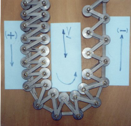 |
The chain column on the right clearly weighs less than the one on the left. The clever linking arrangement keeps it that way, maintaining the overbalanced condition. To understand this, consider the falling chain column on the left, where the chain is compressed. As it goes around the lower pulley, the outer (larger radius) parts of the chain spread apart, allowing the hook links to fall into place by the action of gravity. The links remain in place in the ascending portion of the chain on the right. This maintains this portion of the chain in its expanded, "low density" state. As sections of the chain reach the upper pulley, and begin to go around it, the links simply fall out of position, permitting the chain to shorten to its compressed position as it descends on the left.
You may at first wonder why the links on the left don't stretch out due to their own weight. But observe that they can't because they are stacked up against the links at the bottom that are restrained from "getting ahead" of the links of the expanded chain column at the right.
The latching hooks operate by gravity alone, without altering the energy of the chain by any significant amount.
 |
I love animations of unworkable devices. This nice one is by Jim Mich and used here with his permission. Jim also supplied a correct and clear solution to this problem. For simplicity, the latch links disappear when they unlatch, and re-appear just in time to latch in place. The changing colors of the weights is a clue that may help you solve the puzzle. Watch this animation carefully, for this is the only way you'll ever see this device turning continually at constant speed.
[Note, Nov 11, 2008] When I first received this design from Murilo I thought it was a clever puzzle, or even a joke.
But subsequent email exchanges with the inventor convinced me that he sincerely
believes that it will work, and the photograph he sent me proved to me that
he had already begun to build a prototype. That was several years ago, and he hasn't
reported any success yet. He admits that his skills in this sort of work aren't
up to the task. It is a sad story. Normally I don't reveal names of inventors in
cases such as this, to protect self-deluded people from ridicule, but I subsequently
found that he's proclaiming it to the world through his web site,
AVALANCHEDRIVE - FRCM,
and on web forums that discuss perpetual motion ideas, over-unity devices,
and similar matters. So it is public knowledge now. He has also been annoying people by asking
them for advice, then responding in anger when that advice does not confirm his own preconceptions. His feeble attempts to explain his invention show that he's using a brand of physics of his own invention, physics unknown to anyone else. When people refuse to respond to his pestering, he crows that this just proves that his device must work, and the lack of response is from people's frustration that they can't prove otherwise. You can read Murilo's own account of his invention at his web site, or at the link above, but I doubt that it will help you solve this puzzle. However, the animations are nice, and worth a look.
[Note, May 23, 2009] I received an email from Murilo, full of insulting language directed at me. He's apparently miffed at something he thinks I said, but his incoherent diatribe didn't reveal exactly what. I've been following his contributions to internet forums, where he refers to me by name and says I'm not capable of understanding the subtle principles of his wonderful invention. I have not responded to those. But it is sad to observe that there are people out there who swallow his ridiculous claims and cannot grasp why they are baseless. Not all are taken in. One fellow suggested that Murlio read my website to see why this avalanche drive can't work, but then added "Donald Simanek is debunking stuff so others can make it work." I don't think this person correctly discerned my motivation. My purpose is to educate people about physics so that they can correctly apply it to the real world, and help them to realize that these perpetual motion and over-unity schemes can never work no matter how much you tinker with them.
I see no evidence that Murilo has finished building a prototype. I predicted a couple of years ago that if he did ever make one, it would just sit there, unmoving. I stand by that. Murilo seems to be spending a lot of time defending his ideas on the internet, time that would be better spent building the thing and settling the matter. Like so many perpetual motion ideas, this one seems to be powered by hot air.
[Note, May 31, 2009] Another email from Murilo shows that he's still angry. Now he's accusing me of plagiarizing his design, with my Silly Slinky Device (SSSD). He seems unaware of the implications of this accusation. I clearly stated that my SSSD was deliberately designed to be an example of something that doesn't work. If it were a rip off of Murilo's idea, then he's admitting that his device doesn't work either. My SSSD was one of a number of crazy designs we undergraduates devised for fun, to explore the principles of classical mechanics, back when I was a student at the University of Iowa in the 1950s.
However, since there may be a language barrier here, let me state clearly that I do not claim any priority for Murilo's avalanche drive. The two devices are quite different. His has an articulated chain that acts as a compound lever. Mine does not have that feature. His chain has the same principle as the Roberval balance. My SSSD does not. The only similarity is that both devices are belts over a pulley, but so are many unworkable devices invented and even patented in centuries past. They both are continually heavier on one side of the pulley axle, in any position of rotation. But that fact alone does not make them turn continuously, as I have explained elsewhere on these pages. In fact, both will just sit there, unmoving. I told Murlio that what attracted my attention to his device was the compound lever system in the chain, a feature that was (so far as I know) original, and I give him full credit for that idea, even though it doesn't do anything that could help his device to move perpetually. It's his idea, and a worthless one, and he is welcome to full credit for it.
This puzzle should get your head spinning, but we hope not perpetually.
Buoyant optimism.
 This hydrostatic
wheel was contributed to an English scientific journal in 1831. The inventor
supposed that the floating ball at B would displace liquid, and since "liquids
seek their own level, the levels at A and B are the same. But then there's
more water below that level on the left side, making it heavier, so the wheel
will turn.
This hydrostatic
wheel was contributed to an English scientific journal in 1831. The inventor
supposed that the floating ball at B would displace liquid, and since "liquids
seek their own level, the levels at A and B are the same. But then there's
more water below that level on the left side, making it heavier, so the wheel
will turn.
The errors here are ones that any physics student should see. A floating object displaces its own weight of liquid, and so the weight of material in the tube is the same on the right as it is on the left. Also, water pressure exerts forces perpendicular to the container walls, in this case they are all radial, and can't produce a torque.
Our inventor with the restless mind says "Aha! Submerged bodies displace their own volume of water. If we can just keep that buoyant ball completely under water on the right side, then the left side will be heavier.
 We show such
a system, with a buoyant can B completely underwater on the right side of
the wheel. We could even have vacuum in the can. Clearly there's more weight
on the left of the axle. The water levels are identical. Unfortunately only
water contacts the wheel walls, and that exerts force only perpendicular
to the walls, which is radial. Therefore it can't supply torque to the wheel.
We show such
a system, with a buoyant can B completely underwater on the right side of
the wheel. We could even have vacuum in the can. Clearly there's more weight
on the left of the axle. The water levels are identical. Unfortunately only
water contacts the wheel walls, and that exerts force only perpendicular
to the walls, which is radial. Therefore it can't supply torque to the wheel.
But doesn't the water exert an upward buoyant force on the can B? Yes. And by Newton's third law the can exerts an equal downward force on the water. By Archimedes' principle, that buoyant force is equal to the weight of a volume of water equal to the volume of the can. So as far as the water is concerned, the pressures are the same everywhere as if the can weren't there, replaced by an equal volume of water.
You may have wondered what holds the can in position. If only the buoyant force acts on it, it will rise to the water surface. Something must supply a downward force on the can to keep it in position. That's a little tricky to engineer, to ensure the proper downward force on the can without affecting anything else in the system. But, in view of our analysis above, thinking about such engineering details is wasted effort. Even if we could invent such a can-securing device it wouldn't help our cause.
 |
That was apparently the goal of the person who sent me this drawing. He devised a way to support the can that (he claims) does not exert retarding force on the system (that he says is "unbalanced" and will therefore turn by itself). This is an extremely diabolical and ingenious puzzle on several levels.
How it's supposed to work
Figure 2 (supplied by my correspondent) shows a flexible tube (52) running over two pulleys (50, 58). The tube contains water (64). Inside is an assembly that includes an air- or vacuum-filled can (56) and a stabilizing U-shaped wire (60). This wire and the four rollers (54, 62, and two others) prevent the can from rising due to its buoyancy, keeping it anchored in place. The roller (54) at the top of the can provides even better stability of the can, preventing it from dragging on the tube walls. Since water seeks its own level, the water surfaces in both arms of the tube will be at the same height.
Now it should be perfectly clear to anyone whose mind is not clouded by quantum mechanics that the system is heavier on the left side, so the machine should turn counter-clockwise. The inventor supplies this comparison picture to make that point perfectly clear.
 Of course,
we showed above with the example of the water-filled wheel why the basic
premise is fatally flawed. But if one is simply presented with a full-blown
machine of this complexity one might not see that right away, buried as it
is in complicating details.
Of course,
we showed above with the example of the water-filled wheel why the basic
premise is fatally flawed. But if one is simply presented with a full-blown
machine of this complexity one might not see that right away, buried as it
is in complicating details.
The Wall Crawler
The same correspondent sends me a refreshing return to a purely mechanical device, with no water in it. Fig. 2 shows an assembly of two pulleys G1 and G2 and two gears, in a rigid frame. The two gears do not touch other, but the left one meshes with a vertical rack, as the right one meshes with the right rack. (A rack is a geared strip, with the gear teeth along a straight line.)
The right rack is movable, and an upward force acts to move it upward. Fig. 1 shows how this system acts like a lever, the weight W having a lever arm of 1 unit, the rack and applied force have a lever arm of 4 units. Therefore, assuming the lever weight is negligible, a force analysis shows us that an upward force of W/4 can lift a weight W. In Fig. 2 the same situation obtains, a force of 2.5 kg lifting a weight of 10 kg.
[We are expressing forces in the convenience unit "kilogram-weight" to avoid the necessity of including 9.8 m/s2 in each equation.]
Yet, by analyzing the geometry, when the rack is moved upward a distance d, the weight is lifted a distance d/2. So the work done on the weight is W(d/2) and the work done by the applied force on the rack is (W/4)d, only half as much as is done lifting the weight. So even if the weight of the pulleys, gears rack and frame isn't negligible, there's plenty of work left over for other purposes.
Readers are invited to submit answers.
The Power Amplifier Fallacy.
Recently [2004] the person who proposed the last two devices sent me a new one. He claimed that this was an idea for a machine that would give more power output than input. Before showing it, let's follow his argument. A vertical rod has a sliding platform held in place by rollers C and D. C is simply a guide roller, but D is a motor driven gear engaging gear teeth along the edge of the rod. The motor can drive the platform up or down the rod. A heavy ball is placed on the platform at position A. When the ball is moved to position B, the inventor claims that there will be more torque acting on the rod than when the ball is at point A. We agree.
 |
 |
So, he says that he will use that fact by putting the platform on the edge of a round drum, counter-weighted with a load on the left side. Now, he says that the torque due to the weight on the platform will be communicated to the drum. The motor drives the drum to rotate clockwise, keeping the platform at a constant level. Now move the weight from A to B. This, he says, will give greater torque, communicated to the drum, to increase the effectiveness of the motor.
I have received many cockeyed perpetual motion machine proposals over the last few years, but this one deserves some sort of prize for its combination of so many dubious features implemented with so few moving parts. Most experienced physicists and engineers, and even students of these disciplines, would take one look at it and say "It'll never work!" "It's all screwed up!" But when pressed to identify one flaw that prevents it from working, one hardly knows where to begin:
- In common with all perpetual motion wheels, the distance of weight(s) from the drum's rotation axis does not change or improve the performance.
- It shares with the Roberval balance the feature of a platform on which weights may be placed, but the position of the weight does not matter.
- It looks suspiciously as if the Baron Munchausen fallacy applies (lifting oneself by one's bootstraps). This is also known as the "bootstrap feedback fallacy"
- Like several buoyant engines, it has reaction forces acting on the main drum that pass through the drum's axle, and therefore they exert no torque on the drum.
- The motor driving the drum while at the same time maintaining the platform at a constant position is certainly an unstable situation, requiring some sophisticated feedback system to control the motor speed. However, that's not impossible to engineer. Consider the Segway (TM) personal transportation device.)
- The strange notion that one can gain power by use of an unmoving weight bearing on a gear is a long-ago-discredited idea. It was present in the 1860 Rebour Motor [British patent 1581], and the George Hayes' 1861 "Improved Apparatus for Applying Motive Power" of 1862 [British patent 1112]. It was also the assumed "principle" of the fraudulent Redheffer machine (Philadelphia, 1813) [Ord-Hume 1977, chapter 8].
|
|
Re: Answers left as exercise for the student. Send your answers to the address shown at the right. The earliest good answer(s) that arrive may be posted here, with credit to author. I will post (at my discretion) answers that are simple to explain, clear, correct, perceptive, and that stimulate thinking and further discussion. Posted answers, whether written by me or by others, do not always represent the final word on a given proposal. On several occasions perceptive readers have noticed things we missed, or suggested simpler ways to explain something. So don't hesitate to skeptically rethink given "answers".
While I welcome submission of new or innovative perpetual motion puzzles, I assume no obligation to respond in detail to all of them. In particular, I cannot be expected to analyze vague proposals, overly and unnecessarily complicated designs, nor ideas that are simply variations of classics found in the literature. I've already received proposals that fail for the same reasons already discussed elsewhere on my pages, indicating that the person proposing the idea hadn't fully understood these documents. Also, I choose not to include devices that would require advanced mathematics or physics for detailed analysis. I avoid posting puzzles unless I am reasonably confident what the flaw is, and that the flaw can be explained using elementary physics principles.
Return to the top of this page.
Return to The Museum of Unworkable Devices main gallery.
Return to Donald Simanek's home page.