 | |
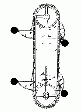
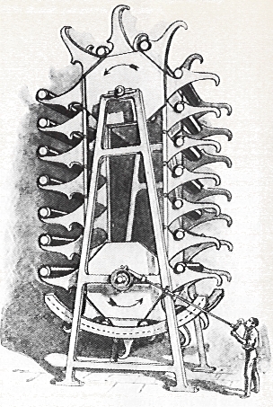
| Fig. 1. Classic overbalanced belt. Drawing by Donald Simanek. |
|---|
Belt and Pulley Devices
In the natural evolution of perpetual motion designs, it seems that wheels came first. Somewhat later inventors employed belts over pulleys. Now this would seem to be a step backward, for belts and pulleys introduce more friction than a simple wheel with a good bearing. The inventors must have had a reason. Inventors don't always state their true line of thinking, especially in patent descriptions. Sometimes they are not consciously aware of their thought development.
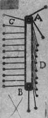 |
| Fig. 2. Bessler's drawing 113. |
|---|
My suspicion is that belts were introduced to give the weights on the belts a greater vertical distance to move up and down, hoping that would increase the weight imbalance or the torque imbalance. Indeed, it can, but it doesn't help the devices to move, and certainly not to initiate movement and sustain it through multiple cycles.
Johann Bessler includes a number of overbalanced pulley designs in his 1733 Maschinen Tractate. Number 113 in that collection is shown in Fig. 2. The drawing was in a group of four similar devices, but, curiously, this one was drawn upside down with respect to the others. Here it is restored to its "correct" orientation for proper operation. :-) A belt runs over pulleys A and B. The weighted bars are hinged so that on one side (C) of the belt they are extended, while they hang unextended on the other side of the belt (D). Supposedly this gives them greater torque on the "extended" side, and therefore sustains a torque overbalance condition that makes it continually rotate counterclockwise. It doesn't.
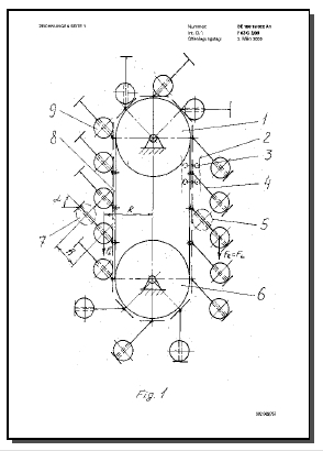 |
| Fig. 3. Frank Walerij's patented device. |
|---|
It's elegantly simple. The belt has segments, with an angled rod rigidly attached to each segment. The angle is about 45°. A weight slides along each rod. On one side the weights slide down the rod and stay at the end of the rod. On the other side they stay near the belt. Clearly the torques are continually greater on the right side, and the longer the belt, the greater this imbalance.
This was unleashed upon the world three years ago, freely available to all seekers of solutions to the energy crisis. But we haven't seen any newspaper reports about it revolutionizing the scientific or engineering worlds. I guess it didn't work as the inventor hoped it would. Darn!
So, readers, explain why this was a failed idea. Keep it simple.
Additional Comments
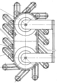 |
| Fig. 4. Frank Walerij device. |
|---|
Here's Frank's description of Fig. 3 above:
Abstract of DE19919022The motor comprises wheels (1,6), a link gear (8), an even number of equal work components (9). The work components in a gravitation motor are heavy bodies, in a hydrostatic motor light floating bodies or air-filled containers, and in an aerostatic motor containers filled with light gas. The work components with the aid of guides (4) are evenly fixed on the link gear (8). The work components, by reason of the guides, which have an angle (alpha) to the radius, roll or slide to the right, and as a result of this the work components to the right of the axes have larger lever arms than those on the left and give rise to a clockwise-rotating motor torque.
Data supplied from the esp@cenet database - Worldwide
 |
| Fig. 5. The Dynamaforce Generator Science and Invention, 1925. |
|---|
We still haven't told you why these don't work, have we? We are waiting for you to send us your solutions.
The classic unbalanced torque belt device.
Fig. 1. above is my attempt to reduce this idea to its essential elements. I've rendered it in 19th century style. Though it is not a genuine 19th century proposal, it has common features of many actual proposals, some patented, and works as well as any of them. The fictional inventor would probably describe it like this.
The four black balls are heavy weights attached to the four clever articulated mechanisms that keep the balls at a larger distance from the axles when they are on the left, and keeps them at a smaller distance when they are on the right. Obviously you could have more of them, for greater power, and have a longer chain, but in any case there will be as many on the left as on the right. Those on the left will have a larger lever arm and therefore supply more torque than those on the right, so the belt should continually rotate counterclockwise. To prevent it accelerating to dangerous speeds, a governor should be attached, or the excess energy could be communicated by a chain, belt or gears to machinery, thereby doing useful work without expenditure for fuel.Of course that description is pure flim-flam and balderdash.
Classification of perpetual motion devices.
One can classify perpetual motion schemes in several ways, but one good way seems to me to focus on the principles implicitly or explicitly assumed by the inventor. The mechanical devices would then be of these types:
- Devices with continual weight overbalance.
- Devices with continual torque overbalance.
- Devices with continual overbalance of both weight and torque.
- Continual force imbalance.
- Momentum imbalance.
Of course the first three of these conditions are achievable, and none of them result in perpetual motion. These represent mistaken "principles" the inventor assumes operating in nature.
- Weight overbalance means that the weight is greater on one side of a rotation axis. This is a real weight difference. The device can even be constructed to continually maintain that weight difference through the device's motion. Geometric constraints ensure that the moving weight's velocity is inversely proportional to the weight, so the work is balanced and the wheel cannot sustain cyclic motion without energy input.
- Torque overbalance means that the torques are apparently greater on one side of the axis. However, it doesn't follow that the sum of all torques is nonzero. The apparent torque imbalance always results from overlooking or neglecting some "hidden" torques acting on the rotating system, usually torques in the bearings. Most of the classic overbalanced wheels had torque imbalance but not weight imbalance.
- Some devices display both weight imbalance and torque imbalance, but since niether condition alone can sustain continual motion, the two together don't either.
- Force imbalance is often the assumed principle of buoyancy machines. It is only apparent, due to overlooking some forces.
- Momentum overbalance would violate Newton's third law. Few examples come to mind. Inventors are usually totally ignorant of Newton's third law. The few devices claiming to operate on this principle are often refered to as "reactionless drives", and their apparent violation of the third law is usually tracable to careless measurements and/or interpretation of measurements. Sometimes this can result from the stick/slip properties of frictional processes.
Thanks to Hans-Peter Gramatke for confirming the German Patent. Hans-Peter has the best web site (in German) on Perpetual Motion Machines. He also has an English version. Thanks also to Martin Gardner for supplying the picture from Science and Invention magazine.
Re: Answers left as exercise for the reader. Send your answers to the address
shown at the right. The
earliest good answer(s) that arrive may be posted here, with credit to author.
I will post (at my discretion) answers that are simple to explain, clear,
correct, perceptive, and that stimulate thinking and further discussion.
Posted answers, whether written by me or by others, do not always represent
the final word on a given proposal. On several occasions perceptive readers
have noticed things we missed, or suggested simpler ways to explain something.
So don't hesitate to skeptically rethink given "answers".
While I welcome submission of new or innovative perpetual motion puzzles,
I assume no obligation to respond in detail to all of them. In particular,
I cannot be expected to analyze vague proposals, overly and unnecssarily
complicated designs, nor ideas which are simply variations of classics found
in the literature. I've already received proposals that fail for the same
reasons already discussed above, indicating that the person proposing the
idea hadn't fully understood this document. Also, I choose not to include
devices that would require advanced mathematics or physics for detailed
analysis. I don't like to post puzzles unless I am reasonably confident that
the flaw can be explained using elementary physics principles.
All material in this museum is © 2002, 2003 by Donald E. Simanek,
with the exception of text and materials indicated as from other sources.
Return to front page.
![]()
Return to the top of this document.
Return to The Museum's Main Gallery.