The Museum of Unworkable Devices
Annex.
 |
Our collection of unworkable devices grows daily. The museum is bursting at the seams with goodies. We've had to contract with architects to design new wings (see the architect's preliminary sketch shown here). To keep costs down, the museum will not have elevators, since visitors can walk on the level from the second floor to the third floor.
Here are some new exhibits and additions to our collection that we think you will find challenging and educational.
This, like many pages at this site, is a work in progress. Expect revisions and addition of new material.
Contents
- Simanek's Silly Slinky Device.
- The underwater bellows wheel.
- The dual-bellows wheel.
- The underwater Hero engine. [NEW]
- The sling accelerator.
- The Simplest Magnetic Motor.
- An Even Simpler Magnetic Motor.
- The ICW Generator.
| An important practical principle of physics: If your analysis of a physical problem allows the possibility of perpetual motion, then you've made a mistake, committed a blunder, or overlooked something important. |
 |
Simanek's Silly Slinky Device
[New, November 2005] Back in the 1950s when I was an undergraduate student, some of us would relax from the rigors of homework by inventing mechanical devices as challenges to each other to figure out why they can't work. I found this one in my classical mechanics notes from those creative times. Here's the description designed to put the best face on it.
Two identical gear wheels (A and B) are connected by a frictionless chain drive (C). Obtain a Slinky ™ toy or two, and make a chain of them to wrap around the outside of these wheels as shown. The coils of the spring engage in the gear teeth, which prevent the coils slipping on the pulleys. The design allows either one or two coils to fit in the gaps between the teeth. we show two coils per gap at the bottom, and one coil per gap at the top.We have arranged things so that the coils are closer together on the right than on the left. We show a compression ratio of 2, but it can be anything you want. The chain drive (C) with ratio 2:1 keeps the lower pulley rotating half as fast as the upper one, maintaining the chosen compression ratio.
The internal forces are clearly balanced, so we need not consider them. Obviously the system is heavier in the right, since there are twice as many spring coils, so we expect the slinky and upper wheel to rotate clockwise. As it turns, the compression ratio will be mainatained, and the unbalance maintained continually. The coils are expanded as they go around the bottom pulley, and compressed as they go around the top pulley, as indicated.
Of course, good engineering design will require two locked coaxial gears (red and blue) at the top and also at the bottom. If you actually build one, its friction may prevent its motion. But it does move freely if either pulley is driven by hand, and it does maintain the condition of overbalance no matter how far you rotate it. Now reduce the friction to zero and watch it go!
 More power! The expected power output is proportional to the weight difference of the two vertical portions of the Slinky Spring. Therefore the power can be increased by increasing the length of the spring and the distance between the pulleys. This improved version is shown in the second figure. There seems to be no limit to the improvement that can be gained in this way.
 Even unworkable devices should be well-engineered.
Suspended springs do not have uniform spacing between loops. That isn't shown in the picture, but it isn't an issue affecting the performance of this device. What's important is that there be more spring loops on one side than the other at all times and therefore more weight on one side. The belt (C) functions to maintain that condition.
What an elegantly simple concept! If we build it, will it turn? As usual, we allow you to use perfect components, frictionless bearings, etc. Discussion and solutions are invited.
Hans-Peter Gramatke noticed an error in my original picture and sent several good solutions, which we'll save for later. Hans-Peter also made improvements to the device, employing good German engineering. He supplied the marvelous animation shown here, in which the lower gear has twice as many teeth as the upper one, and the chain drive is arranged to drive the lower gear half as fast. This arrangement is certainly better, ensuring smoother motion and more secure alignment of coils and gear teeth. [The slight irregularity of gear speeds is due to coils sliding over the gear teeth. Hans-Peter, always the perfectionist, is redisigning the gears for smoother operation. Until then he's put a flexible clutch in one of the gears.]
The underwater bellows wheel
 |
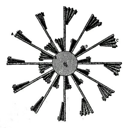
Here's a nice puzzle we created by "improving" a very old idea that appeared in Recreations in Science and Natural Philosophy by Jacques Ozanam (1640-1717). [Editions of Hutton (1803) and Riddle (1854)]. A wheel has eight hollow arms terminated in bellows. On each bellows is fastened a lead weight. The air chamber in each bellows communicates through the hollow arms to the bellows directly opposite. (This is not clearly shown in the diagram.) Compressing one bellows forces air to expand the opposite bellows, and vice versa. The center of the hub is the axle of rotation.
Now we put the entire thing underwater. On the left side the bellows will compress due to the weight of the balls. On the right side they will expand for the same reason. Now every physics student knows Archimedes' Principle: "A body immersed in liquid experiences and upward buoyant force equal to the weight of the displaced liquid." The displaced liquid is an amount of liquid having volume equal to the volume of the body immersed in the liquid.
So, on the right the bellows are more "open" and occupy a larger volume, so these will experience a larger upward buoyant force than the bellows on the left that occupy a smaller volume. The wheel should therefore rotate counterclockwise continually.
If you think this is a goofy idea, then:
- Explain why it can't work, using elementary freshman physics.
- Explain why in 2001 French Patent No. 2,830,575 was granted to Smeretchanski Mikhail for a device using the very same principle. He describes it as "A device for the production of mechanical energy..., using elements with variable volume and the force of Archimedes for its operation."
- 1857 British patent No. 1330. Peter Armand le Comte de Fontainemoreau of London, Agent. Hydraulic motor.
- Jan 27, 1976. David Diamond. US patent 3,934,964. Gravity-Actuated Fluid Displacement Power Generator.
- 2001 Smeretchanski Mikhail. French Patent No. 2,830,575.
Answer and discussion of this misconception.
The dual-bellows wheel
 Here's an earlier version of the bellows idea, reduced to its simplest
form. It's still more evidence that unworkable ideas have an inexplicable
fascination for restless minds. Just when we think we've seen all
variations of this idea, new ones are found. Someone has estimated
that 90% of all patents are only minor variations of existing patents.
This certainly seems true of PMM patents as well.
Here's an earlier version of the bellows idea, reduced to its simplest
form. It's still more evidence that unworkable ideas have an inexplicable
fascination for restless minds. Just when we think we've seen all
variations of this idea, new ones are found. Someone has estimated
that 90% of all patents are only minor variations of existing patents.
This certainly seems true of PMM patents as well.The source we swiped this picture from didn't provide documentation, and the author didn't seem to understand exactly how it was supposed to work. We can imagine two ways to use this wheel, both ineffective. In both cases the little protuberances on each bellows represent lead weights.
-
The arms are independent, and the bellows and shafts on each arm are
filled with a liquid. In the position shown the weights on the arm
at the right have compressed the inner bellows and expanded the outer
bellows, so that the liquid inside is shifted to a larger radius.
On the left arm, the outer bellows is compressed and the inner one
is expanded by the weights, so that the fluid inside is shifted to
a smaller radius. Result: the classic "continually overbalanced wheel",
and the wheel should turn clockwise.
-
The arms are independent, and the bellows and shafts on each arm are
filled with air. The entire wheel is immersed in a tank of liquid.
In the position shown, the weights on the arm at the right have
compressed the inner bellows and expanded the outer bellows, so that
the net buoyant force on the air-filled bellows is shifted to a larger radius.
On the left arm, the outer bellows is compressed and the inner one
is expanded by the weights so that the net buoyant force on the air-filled
bellows is shifted to a smaller radius.
The wheel should turn counter-clockwise.
Similar devices.
Answer and discussion of this misconception.
The underwater Hero engine.
 |
The first known description of a steam powered engine was that of Hero(n) of Alexandria. It spun around like a water sprinkler, driven not by pressured water, but by steam pressure.
Here's a perversion of that idea, a rare self-powered spinning device that uses the principle of a jet engine. Val Makotinsky contributed this clever puzzle. It incorporates design features that are novel in the literature of unworkable devices. It even has distractors that look "fishy" but aren't the real reason why this won't work. (They would be a problem if this thing were turning continually, but it won't do that.)
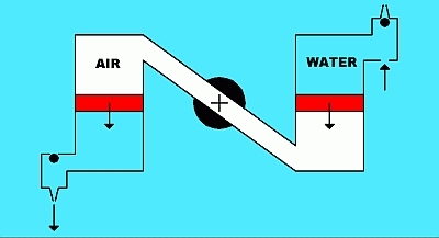
The actual engine would have an even number of chambers, of which we show only two. Opposite ones are connected by a tube so that air (white) can freely flow from one to the other. Each has a heavy piston (red) with the usual frictionless seals that we generously allow in these puzzles. The whole thing is immersed in water (blue-green) that can enter the piston chambers by either of two holes, one hole having a nozzle for increasing the velocity of water exiting from it. Balls (black), lighter than water, rise upward to block one of those holes, whichever is "up" at the time.
Now see how diabolically clever this is. In the position shown, the left piston is pushing down on the water, which exits the jet, giving thrust. The ball closes the other hole. The right piston is also moving down, but the ball closes the jet hole, leaving the other hole open to admit water. So the jet causes the whole thing to rotate clockwise.
 |
One perceptive reader asks "Why use air in the inner chamber?" It just complicates things because it is compressible. Why not use some less compressible fluid instead? Indeed, why not replace the air with water, which is only very slightly compressible? Good idea. The conundrum still remains. The heavy pistons would surely fall, forcing water out of the jets. What would this do? Would it cause the system to rotate? Would it rotate enough to invert itself (and invert the pistons) so that the rotation could continue, perhaps perpetually? Inquiring minds want to know.
Unworkable devices should be simplified as much as possible, even if this doesn't improve their performance. But it can make them appear more plausible.
So now just lower the device into a large water tank and watch it take off and spin forever. No steam required. Maybe.
Before sending in your answer, do a little research on the classic "reverse water sprinkler" described in Ernst Mach's "The Science of Mechanics" (first German edition 1883). It is also discussed on many web sites and web forums.
The sling accelerator.
Ken Amis likes to tease people with outrageous inventions. He sends us this one that is difficult to classify. He's outspoken in his view that inventing mechanical perpetual motion machines is a waste of time, for they never work. So he challenges our readers to find the flaw in this idea. We'll let him explain it in his own words.
I like simple devices. This one has a vertical axle labeled AXLE. A mass m is attached to an inextensible but flexible string that fastens to the axle at C. The diagram shows the motion in a horizontal plane (so we don't have to mess with gravitational effects). Initially the mass is at point A, and is moving to the right quite fast, since we gave it a push to get it started. At this time the axle is locked in place and doesn't rotate. As the mass goes around the axle clockwise, the string wraps around the axle, shortening the free portion of the string and causing the mass to move along the spiral curve AB. At point C, we have a device (not shown) that senses the string's arrival and releases a catch to allow the axle to rotate exactly one revolution, when the catch stops it. (Yes, this device has a catch. Don't expect me to draw its details; design one yourself.) As the axle rotates quickly, the string unwinds and the mass is allowed to move to a larger radius, from B to A.
It's plain to see that as the mass spirals inward from A to B, its speed increases. When the catch releases, work is done as the mass moves from B to A, due to the tension force in the string having a component in the direction of the motion of the mass. This tension does work turning the axle during this short time interval. We steal a little energy from the axle's sudden rotation, to do useful work. Sure, the power is intermittent, but so is the power released to a mechanical clock, and that can be smoothed and regulated as necessary.
A hint. Do not look at the hint until you've thought it through yourself. If that fails, here's my my answer.
The Simplest
Magnetic Motor.
Lots of people have been trying to make magnetic motor perpetual motion machines. Their designs are often Baroque in their complexity. In a generous spirit I have designed this, one of the simplest magnetic overbalanced wheels one can build.
The stationary axle (A) has one fixed magnet inside it. The larger wheel (B) can rotate and has a number of magnets (blue) free to slide radially in frictionless chambers. This wheel turns on the axle without friction. The wheel is in a vertical plane to take advantage of gravity.
As anyone can clearly see, the magnets on the right will be pushed outward by the magnet in the axle, the magnets on the left will be attracted to their smallest radial distance. Therefore the wheel is continually heavier on the right side of the axle and should turn in the direction shown by the arrow.
Some may be concerned about centrifugal effects due to rotation, which would cause the magnets to move radially outward in their slots. That's not a concern at slow speeds, for the magnets will still be overbalanced on one side, and this device doesn't achieve high speeds. If it's a problem, the fix is to simply use springs on the movable magnets, on the inner side of the chambers, to provide enough centripetal force to keep the average magnet position within bounds for a chosen speed, then regulate that speed with a governor. Isn't engineering marvelous?
Those perverse folks who think this won't work are invited to explain the flaw in this design, using elementary physics only. See the email address at the bottom of this document.
An Even Simpler
Magnetic Motor.
A correspondent was inspired by The Classic Magnet Motor in our main gallery, but thought the shields were a bit much, and unnecessary. So he suggested this simpler device. First, to produce smoother rotation, make a large cylinder magnet with a cylindrical hole down the center. Then put a smaller horseshoe magnet inside it, as shown, attached to a shaft (black dot) running down the axis of the outer magnet. We show just one end of the apparatus, the N polarity end. Imagine, as in The Classic Magnetic Motor, a similar arrangement on the same shaft at the other end, with another horseshoe magnet, so the two will turn in the same direction.
Clearly the N end of the horseshoe magnet will be repelled by being in such close proximity to the outer magnet's North end. Likewise, the S end of the horseshoe magnet will be attracted to the outer magnet's North end. We supply helpful arrows to show the directions of these two forces.
So the horseshoe magnet will experience a counterclockwise torque, which will be the same size for any position of the horseshoe magnet, and therefore will sustain its motion.
The ICW Generator.
[New, August 2002] This device was submitted by Jon B. Davidson, who also provided a helpful animated GIF to help you visualize how it operates. This color picture is mine, and I hope it doesn't misrepresent the inventor's intent.
Two buoyant carriers C1 and C2 ride inside the liquid filled tube. Two heavy lead balls, 1 and 2 can fit into them. Each carrier is buoyant enough to rise in the liquid even with a lead ball in it. A sliding "stop" B (green) holds the lowest carrier at the center of rotation of the apparatus, whichever one happens to be the lower one. Carrier C1 will push this to the dotted position A when the apparatus is inverted. The inventor had a system of pegs to accomplish this. Of course the sliding of stop B is frictionless.
 In the position
shown, ball 1 can roll down the sidearm at tube end Y, thus overbalancing
the system so it turns clockwise. Ball 2 just sits in carrier C2 at the center.
When the system has turned 180° ball 1 rolls back into its carrier again,
tripping a mechanism that releases the carrier C1 so it can rise. At the
same time, carrier C2 is allowed to rise to the top, releasing ball 2 into
the sidearm.
In the position
shown, ball 1 can roll down the sidearm at tube end Y, thus overbalancing
the system so it turns clockwise. Ball 2 just sits in carrier C2 at the center.
When the system has turned 180° ball 1 rolls back into its carrier again,
tripping a mechanism that releases the carrier C1 so it can rise. At the
same time, carrier C2 is allowed to rise to the top, releasing ball 2 into
the sidearm.
The inventor's animated GIF should make this sequence of events clear. The catches that temporarily hold the carriers in place can be activated by very sensitive detectors, and timed if necessary. Similar "catches" engage to prevent any backward motion of the apparatus, ensuring everything always moves clockwise. The system can be held stationary till the upper ball reaches the end of its sidearm, when it triggers the release of that catch. These are engineering details that need not concern us overmuch, and surely can be made to require very little energy to operate. The animation includes these momentary "halts" of the motion, which also makes the analysis simpler, for we needn't get involved with centrifugal effects as the balls roll down to the ends of the tubes.
As usual, we let you use fluid that has zero viscosity. We invite your solutions. Why won't this work?
All material in this museum is © 2002, 2005, 2011 by Donald E. Simanek, with the exception of text and materials indicated as from other sources.
Return to front page.
Return to the top of this document.
Return to The Museum's Main Gallery.