Patrick Voet's Perpetuum Mobile Machine
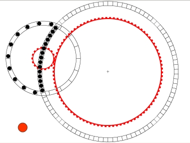 |
The left wheel turns clockwise. The right wheel turns counter-clockwise. In a given time N balls are delivered and transferred from the left to the right wheel at the top. In that same time N balls are transferred back to the left wheel at the bottom. So N balls are lifted a height H and allowed to fall the same height H. The net work is zero, even though on the left the balls are separated farther apart, and go a greater linear distance, it's the height changes that matter, determining the work done. Clicking on the red button reverses everything, and it looks just as good, even though this reverses the role of the wheels as to which is the "source". The red gears keep everything in sync, just as does the "timing belt" in my silly slinky device.
An Old Idea
This device is seldom seen today, but it is an old idea. The earliest example that I know of is from Johann Bessler's 1733 Maschinen Tractate. It is No. 44 in that collection.

No. 44: The sphere-method is reintroduced here. The problem shows 2 wheels: A is the main wheel, the axle of which has a gear at B. B drives the somewhat larger wheel C at point D. At side E are spheres which fall out of side G at point H below and into wheel C at point I and then out of C again into A at point F. This problem looks good, but as sketched it does nothing special as long as no other application is present, for the wheel A must revolve several times before C revolves a single time. Thus not enough spheres move from the former into the latter.This illustration is redrawn from the faded original and is © by Bill McMurtry. See his website Orffyreus Returns—Johann Bessler
Bessler's note for this design cleverly evades the real issue, but his comment that it "does nothing special" is right on target. The gear B is the hub of wheel G (spokes are not shown) and therefore B and G are constrained to rotate at the same rate. Many (most) of the machines in Maschinen Tractate were from other sources Bessler had seen, and this is one of several (Nos. 44 through 49) variants of this idea that he includes. Yet it isn't clear that he depicted them correctly, nor is it clear that he understood their assumed operating principles.
This is an example of what I call "forced overbalance". The weight(s) are kept in apparent overbalance by the red gear linkage. This has several problems. There are indeed more balls on the left of the right wheel's axle, so it appars overbalanced, and that impression dominates one's judgment. But the left wheel has more weight on the left of its axle, so it is overbalanced, too, but it seems to be turning the "wrong" direction. The overbalance simply doesn't initiate or sustain motion, as we have seen in many examples before.
Any continual imbalance or overbalance must be sustained by forces, and one may forget to inquire about them. If anything did move, forces must be doing work, and that work must be supplied from somwewhere.
Return to the New Acquisitions Gallery.