Physics Toys, Tricks and Teasers
The Frugal Physicist's Demo Collection,
by Donald E. Simanek
Fun projects you can build from everyday materials at small expense.The web has many sites featuring easy-to-make physics toys, and many books of them may be purchased. In this document I feature curious and puzzling items that are not so well known, and some of my own invention. Some of these are not exactly clear-cut demos of physics principles, but are fun things to do. A larger collection of my favorite standard physics demos, of the kind intended to clearly expose simple physics principles, may be found on my physics demos document.
CHEAP SPECTRA
[May, 2004] Students best understand light spectra when they can do hands-on investigation of spectra of common light sources. Spectroscopy with prisms or diffraction gratings can be expensive. Inexpensive plastic gratings, and holographic gratings are available from science supply houses. Students can use these to directly observe incandescent lights, fluorescent lights, and gas-filled Geissler tubes. The Geissler tubes operate from a high voltage power supply of the sort used for "neon" advertising signs. But these signs, and the Geissler tubes) have gas-filled tubes of mercury, hydrogen, argon, air, and neon.The Geissler tubes are rather expensive now, must be handled with care, and have limited useful lifetime. High schools may find the expense too great. Is there a cheaper and better way to learn about spectra?
 |
| 40 watt tube fluorescent photographed using only a diffraction grating in front of a digital camera. |
|---|
Direct visual observation of light sources through a diffraction grating cannot resolve fine details of the spectra, because of the angular breadth of the source. One can pass the light through a narrow slit first, but that's a bit tricky to set up. Even the Geissler tubes, though they have a narrow glowing area, are still not as narrow a source as we'd like. Also, one should never look toward bright sources, especially those emitting ultraviolet, such as arc lamps and the sun.
|
Fortunately there is an easy way around these problems. It's an old idea, virtually unknown to physics teachers today. Create a "virtual slit" using a sewing needle. It was originally used with a prism to view the Fraunhoffer spectrum of the sun safely. Used that way it was a bit clumsy to set up. But with modern holographic gratings, the idea can be adapted into a very neat way to observe any spectrum.
The figure shows the method. A smooth polished rod or needle is placed against a black background. Black velvet is best. The rod acts as a cylindrical mirror, receiving light from the source (behind the viewer's head)and forming an elongated virtual image of the source very near the needle. This image is demagnified, so that the width of the image is very much reduced, and the image acts like a "slit" source. In this arrangement the light source is behind the observer, and there's no danger of looking directly at it.
Light from a distant object formas a virtual image located halfway between the surface of the rod and its center. The angular magnification of the mirror is 0.5. The light that actually reaches your eye, or the camera lens, is linmited to a very narrow range of angles, so the effective "slit width" is very much smaller than the rod's diameter.A grating, G, is placed before the observer's eye. A spectrum will be seen against the black background. The same method may be used to photograph the spectrum. Focus the camera at the distance of the rod. The example below is a photo of the spectrum of a compact fluorescent lamp, "150 watt" ouput. The photo shows two blue lines, a green and a red of the mercury spectrum. The mercury yellow line is quite faint, and other faint yellow and red lines nearby are fluorescent emission from the phosphor coating of the lamp. To the left of the green is a band of green lines, also from the phosphor.
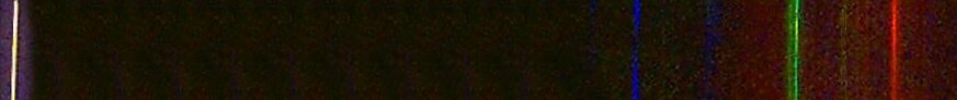 |
| Spectrum of a compact fluorescent lamp. |
|---|
The needle (at the left of the picture) was a Dritz "Doll Needle" 8 cm long and about 1 mm diameter. The needle and black velvet backdrop were 5 ft from the camera, and the light, behind the camera, was 5 feet from the needle. Stores that sell crafts, fabrics and sewing supplies have such needles. Pick some up when you buy the black velvet.
|

Digital cameras do not reproduce pure spectral colors well. Also, photographs of spectra taken with cameras designed for pictorial photography do not record well the wide range of brightness, and therefore lose the fine detail and subtlety you can see with your eye. This digital photo shows only a suggestion of many of the Fraunhoffer absorption lines of the solar spectrum. It was made with the apparatus here described. With the same setup and the eye alone, one can see at least a dozen very narrow, dark absorption lines. Never look at the sun directly or with telescope or binoculars. Always use a method that reduces the light intensity, as the needle method does automatically.
Exposure. In a dark room, digital and auto-exposure cameras will default to their largest lens aperture and slowest shutter speed. Therefore the camera and the rod must be on solid supports. Outdoors, in daylight, auto-exposure may underexpose the spectrum, unless light from everything else is excluded by opaque screens.
Science supply stores like to sell holographic grating material in rolls and large amounts, enough for a large science class. You need only a piece about 2 inches square, or less. Small kits may be purchased from Learning Technologies, Inc.
TUMBLING RING ILLUSION
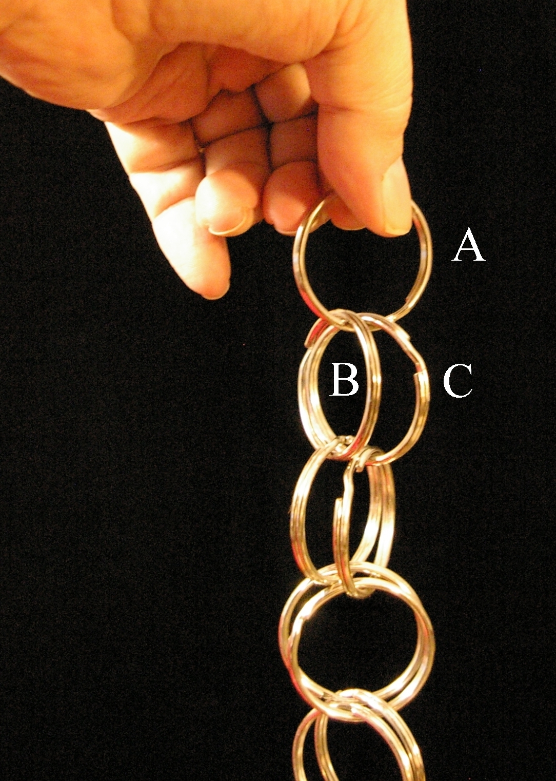 |
| The tumbling rings. Use this as a construction guide. |
|---|
[Aug 2001] This one comes from an old book of tricks for entertaining. It appeared in Martin Gardner's "Mathematical Games" column in the 1950s. An even number of rings are interlinked as shown in the diagrams. I first used split key rings which can be found in several sizes in craft shops and key shops. If you hold the top ring (A), test the rings just below by trying to lift one of the two rings below it. One of them can be lifted and cause the entire half-chain below to lift with it. Hang onto that one ("B" in the diagram) and let go the other one. You may be rewarded by a sequential falling action which looks to the audience like the top ring fell all the way to the bottom. Actually, the other side of the chain untwists, giving an illusion of a falling ring. If this doesn't happen, you have grasped the second ring on the wrong side. Try it the other way.
Once you get the hang of it you can keep a tumbling action going by transfering your hold from the top ring to the next after each fall, timing your action to the period of fall. At any step, there are four places you can grasp rings below, three of them are wrong. Suppose grasping the left ring near you works. Then the next time grasp the right ring at the point farthest from you and keep alternating this action.
I have made larger sets using plastic rings from craft stores, the kind that can be opened at a locking socket, linked and then re-locked. I have also made a set using craft-store 7 inch steel rings. Half of the rings must be sawed open at the weld point with a hack saw. Assemble the ring chain then weld the breaks closed. File off irregularities due to the welds. This is about the limit of ring size for good performance. Larger sets fall too slowly, and the illusion is destroyed.
Assembled chains with 5 inch diameter rings may be bought at magician's shops. They are sometimes called the "Afghan Rings".
For a more complete description see Kinetic Illusion Toys.
SPINNING CYLINDER
 |
[May 2000] Martin Gardner introduced me to this one. He couldn't recall who gave it to him, or whether it had a name. He hadn't seen any reference to it in print, but supposed it was "well known to physicists". This may not be the case.
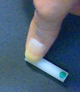 |
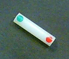
This little toy has only one moving part and doesn't require batteries. It is easily made. It's just a hollow cylinder of rigid plastic. This one is 4 cm long, 1 cm in diameter and 2 mm wall thickness. I made this one from the plastic pipe sold in hardware stores for the inlet water supply of a toilet tank. Be sure to choose a straight one. They can be cut with a single-edged razor blade, scrap wooden board and a hammer. Use heavy gloves and goggles. Or use a hack saw and smooth up the cut with fine sandpaper. Cut the cylinder initially a bit long, then trim it to optimum length by trial. I've made these in 2, 3, 4, and 5 cm lengths. I've also made some from old ballpoint pens, and larger ones from PVC plumbing pipe. Glue or paint a red dot near one end, a green dot at the other end.
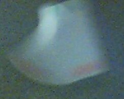
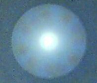
Place the cylinder on a flat surface. Press down on one end with finger or thumb until the cylinder slips away and flies off spinning. It will settle down at one place, spinning about its midpoint and at the same time spinning about its long axis. Here's a sequence of actual photos showing it (1) beginning to spin, (2) when it hasn't quite settled down, and (3) when it is spining in one place with nearly constant angular speed. These photos were made with a digital camera, the light level being low enough to force a shutter speed longer than the rotation period. This is about the way it appears to the eye.
| 
| 
|
The fascinating outcome is that when the cylinder settles down to a uniform spin rate at a particular location on the table, you see only one of the colored dots (red in this case), repeated N times, where N is the ratio of the cylinder's length to diameter. The dot you see is the one at the end you pressed with your finger to launch it. You do not see any evidence of the dot at the other end (green in this case). Launch the cylinder by pressing the green dot end and you see only the green dot, and don't see the red one. The puzzle is to explain this behavior.
When you think you have it figured out, test your understanding by considering this follow-up. If you spun this toy on a glass sheet, and had someone looking up at it from below the glass, which colored dot would that observer see?
What would the optimum length/diameter ratio be for a given number of dot repetitions if you used a solid cylinder? (It may not be the same.) What role does moment of inertia play here? Friction? Energy? Lots of physics here to address, and it may not be easy to do.
More detailed observations. A 3:1 version with 3/4" PVC pipe works best for these. This larger version also seems to exhibit less translational motion from the point of launch before stabilizing, enabling you do do the experiments on a smaller surface area. Spin the cylinder by launching it forcefully at the red dot end and observe it from the side. For a while it spins with the red dot end rather high in the air. During that time you may see a brief but stable pattern of 5 red dots. It slows and spins with the red dot end only a little bit above the table, and then you see a pattern of three dots for a longer period of stability. During the transition you do not observe a stable pattern of four dots, except perhaps fleetingly. Are you surprised?
Note that translational motion of the center of mass stops just before stable dot patterns emerge. Note also (from the photographs, or from observation) that what we call the "stable motion" is such that both ends traverse a common circle. In the case of five dots seen with the 3:1 cylinder, the high end traverses a larger circle, while the smaller end makes a smaller circle. Two web sites assert that in the stable spin cases only one end of the cylinder touches the table, and that end is rolling without slipping. Do you agree? Why should that happen?
When the stable 3-dot pattern is observed, the cylinder seems to be rotating about its center, the two ends traversing the same circle (see the photos). I've identified two web links which describe this device, with pictures.
These sites give only partial answers. They assume that the cylinder moves with only one end in contact with the table. They do not address the question of why the length/diameter ratio must be different for a solid cylinder than for a hollow one. Clearly the moments of inertia must also play a role, and the solid cylinder is not moving with only one end contacting the table, or perhaps the end contacting the table is sliding.
Equally interesting devices based on rotational physics have gotten complete mathematical and physical analyses in print, and even have names: "tippy-rop" and "rattleback". Why does this neat toy seem to have no unique name, and apparently no complete analysis? In the spirit of stage magician's "cutsey" names for tricks, I suggest this one be called "Dots Elusive".
This toy has at least one feature in common with the tippy-top. When the cylinder is launched forcefully enough, it comes very close to spinning on one end for a short while. That means that its center of mass has risen nearly half its own length! The tippy-top turns completely over and spins with stability for quite a long time with elevated center of mass.
SIMANEK'S PENETRATING MAGNETS ILLUSION.
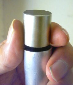
[Feb 2004] Have you noticed toys marketed these days with names such as "Newton's gizmo", "Newton's Cradle" "Newton's Gravity Glass", or something with Newton's name in it, when in fact, Newton never even saw some of these toys? So, following tradition, I'm torn between calling this demo "Newton's Magnets", or "Simanek's Penetrating Magnet's Illusion". For the record, I devised this on Jan 14, 2004, having never seen it described in print or on the internet previously. Why should Newton get all the credit, hadn't he done enough already?Obtain a dozen or so of those small, flat ceramic magnets, 1 inch diameter, 1/4 inch thick with a 3/8 inch hole in the center. You can get them at Radio Shack, craft stores, hardware stores, etc. You don't need a whole dozen, but extras are good to have in case of breakage.
 |
Thread five of these, with alternately opposing polarity, on an 1/4 inch aluminum or plastic curtain rod, about 3 feet long. Such rod can also be purchased in hardware stores. I put rubber washers on the end of the rod, so the magnets won't slide off the ends. Don't use a steel or iron rod. Plastic rod is good, but it should be smooth and rigid. A wooden dowel is not as good, unless sanded very smooth, and perhaps, varnished.
For a "magic trick" routine, you might begin this way. "Magnets are fascinating things, and they behave in unexpected ways. I will show you a little-known property of magnets, which actually allows them to penetrate through one another—under proper conditions, of course."
Now hold the rod in a horizontal position. Spread out the magnets in the middle, so they are about equally spaced. Jiggle the rod so they find a position they "like". (Actually this spaces them so their magnetic repulsion is just about equal to the sliding friction.) Move the magnet at the left end away from the others, and then with two fingers behind it, propel it forcefully toward the others, so it hits with enough speed that you hear at least one collision. Before doing it, say you are going to make it "pass right through" the others without disturbing their position. Suggest to the spectators that they watch carefully the positions of the magnets. Now do it. Your claim seems to have actually happened, for one magnet seems to have gone all the way through, and the rest are in the same positions as initially. But in fact, the magnets end up in the positions that the stationary ones occupied before. The first two pictures in the figure show this.
Now say, "Maybe you didn't see that, it happened so quickly." So reverse the action, by taking the one that seemingly passed through and propel it back toward the others. Same result: the others didn't seem to budge, but everyone heard noise as it "went through".
Now someone will suspsect that the magnets just changed positions somehow. So this time start with the magnets in the center equally spaced except that you enlarge the spacing between two of them. Tell everyone to watch that larger spaced gap. Do it again, and after the magnet passes trough, the larger spaced gap is still there. The last two pictures in the figure show this.
Yes, you will occasionally crack a magnet, or knock a chip out of one, so have extras on hand. When this happens, just say "Sometimes, if the atoms aren't all perfectly aligned. They can't quite squeeze through the spaces between them, and one magnet is so stressed that it cracks." After discarding ones which chip or break, the remaining ones are probably the sturdiest ones. (Survival of the fittest?)
This demo is more fun than the Newton cradle, and a lot easier to keep in adjustment. You do need to encourage the audience to watch carefully whether the stationary ones change position. Tell them to listen to the sound as it collides. People are not normally observant of small details unless encouraged and told what to look for. A little practice will give you the "feel" of the best starting speed.
When I first played with this some years ago, I didn't discover this neat illusion (magic trick) because I was always being careful to avoid actual collisions of the magnets, thinking I might break them. So my caution prevented me using a larger speed and discovering how strong the illusion is when done properly and forcefully.
Ah, but now to explain it! Why does the additional gap seem to be preserved (wherever you make the gap and whichever direction the moving magnet goes). Clearly there's energy loss to friction. Is this part of the reason this works? Or does friction even matter? I have marked the initial position of magnets on the rod with a lead pencil, and find that the final positions of the stationary magnets are usually less than a millimeter different from the marked positions.
I haven't tried it yet, but I suspect that one could cover the magnet faces with felt and get results just as good, with less concern about breakage.
Just because the behavior of this toy is "something like" the classic Newton's Cradle doesn't mean the two are alike in all details. Newton's Cradle doesn't have friction. The balls do not exchange positions. As usual, if I get any good, simple explanations, I'll post them here.
ROLLING SPOOL
 |
A spool (or yo-yo) has a string wrapped around its spindle. It rests on a table, with the string emerging from below the axle. When the string is pulled horizontally to the right (see diagram) which way will the spool roll?
It rolls to the right while rotating clockwise, if friction is sufficient to prevent it slipping on the table. The string winds up on the axle, so the spool moves to meet your hand as you pull on the string.
Now this gets more interesting. Raise the angle of string as you pull. At some critical angle, the spool will slide along the table without rotating. If you do this with a real spool, you will need to carefully maintain that constant angle as you pull. What is that critical angle?
 |
If the angle is larger than the critical angle, the spool will roll in the opposite direction.
The free-body force diagram of the spool is easy to draw. The forces acting on it are (1) the gravitational force on the spool downward, (2) the upward normal force of the table on the spool (3) the force due to string tension, (4) the force due to friction at the table surface.
All of these are "unknowns". We assume we are dealing with a non-accelerating system, where linear motion and rotation are at constant speed. So we can use the fact that the net force is zero and the net torque is zero. By choosing a center of torques at the point of contact with the table, we eliminate the unknown weight, normal force, and force due to friction from the torque equation! We conclude that the torque due to the string, Tr is zero only when its line of action passes through the center of torques. Therefore the angle of the string with respect to the vertical is given by sin(θ) = r/R where R is the outer radius of the spool and r is the axle radius. We might call this the formula for the spool sliding without rolling.
So far this has been a standard physics demonstration and problem. Here's a follow-up. Ask students to consider a solid cylinder with a mylar tape wrapped round it. [1" wide computer magnetic recording tape works well.] The tape emerges at the table top and is pulled in a direction parallel to the table. Students try to apply the formula they just derived, and are stumped. The spool radius and the axle radius are identical, so application of the derived formula gives sin(θ) = 1 or θ = 90°. We predict that when we pull the tape parallel to the table the spool will slide without rolling.
This illustrates the dangers of applying a formula without understanding what went into its derivation. If we try the experiment the likely result is that the spool will roll away opposite to the direction we pull. Now the question for students is "Why?"
THE MISMATCHED TUBES
[April 2004] Prepare two metal tubes. Mine are cut from 1 inch diameter aluminum tubing from the hardware store. One tube is 11 inches long. The other is 1/4 inch shorter. Try to ensure that the tubes have no scratches or imperfections that could distinguish one from the other.Hold them up, one in each hand, and ask if anyone can visually see that one is shorter than the other. Of course no one can. Hold them side by side, touching, and the difference is obvious. Ask someone to take them, then turn around to hide them from your sight, choose one, and then hand it to you. You pretend to judge its length between your hands, touching the tube at its ends, only with your fingertips. Set it aside and ask for the other, doing the same, then announce "This one is (shorter/longer as the case may be)."
You could do this blindfolded, but that's probably overdoing it for a physics demo.
Secret. As you handle the tube, you slide your fingers around the rim. If the room is quiet you can hear the tube "sing" at its resonant frequency. Probably no one else will hear it. The tube with the lower pitch is the longest. The ears can distinguish the length difference better than the hands. The pitch difference is about one semitone, easily noted by most people. As always, practice first.
In physics class, you should then demonstrate this for all to hear. Hold a tube between thumb and third finger about 2.5 inches from one end (a vibrational nodal point) then tap the other end with a fingernail.
THE SLOW FALL
|
[April 2004] Neodymium Iron Boron (NdFeB) rare earth magnets are becoming easily available and relatively inexpensive. Such a magnet, when dropped down a non-ferrous metal tube, will descend very slowly. Complete apparatus for this experiment can be purchased from scientific supply houses. It has about a 5 foot long aluminum tube and a cylindrical magnet. But you can make your own apparatus for less cost.
One inch aluminum tubing is available in hardware stores in 6 foot lengths. A 3/4 inch diamter cylindrical magnet fits loosely inside. The effect is clearly demonstrated with no more than a 10 or 12 inch long tube. 1/2 inch OD copper tube may be used with a 7/16 inch diameter magnet. Why does the magnet fall so slowly?
If the magnet is small enough, it can be dropped down the tube in any orientation. Note that if you drop it in edgewise, it will probably turn as it falls until it emerges oriented with its poles along the up/down line. Why?
The reason. The moving field of the magnet exerts forces on electrons in the metal tube, setting up induced currents. Moving electrons have a magnetic field of strength proportional to their speed. This magnetic field of all the moving electrons acts to oppose the motion of the magnet. It is an example of Lenz's law: A changing magnetic field produces currents whose fields act to oppose the change of field.
So the magnet moving down is opposed by these induced currents whose field exerts an upward force on the magnet. The size of the currents quickly increases until the upward force on the magnet matches the downward force due to gravity. But by the time this happens, the magnet is moving down, and continues to move down at constant speed, since the net force on it is zero.
Falling sphere. Magnetized nickel-plated rare earth spheres are also available from many internet sources. Obtain such a sphere and an aluminum tube that are closely matched in size, and the sphere will fall slowly down the tube just as the cylinder did. Mark the magnet "poles" with small colored stickers. Now watch the sphere from above as it falls down the tube. Does the sphere always rotate and re-orient so that one of the poles is up, and the other down? Or does it re-orient with the magnetic axis horizontal? Why?
Caution! These magnets are very strong compared to their weight, and can affect objects more than a foot away. Do not place them near credit cards, computers, VCRs, TVs, pacemakers, computer disks, magnetic tape, or any magnetic computer storage media. The nickel plating does prevent scratching and chipping of the magnets, but they are fragile, and should not be allowed to strike each other, or other objects, for small chips could fly off.Treat small magnets just as you treat prescription drugs: do not put them where children can find them, for children will put anything in their mouths. A swallowed magnet will pass, but if two magnets are swallowed separately, or a magnet and a ferrous metal object, they can be attracted to each other with an intestinal wall between, and perforate the intestine.
THE VISIBLE SLOW FALL
|
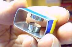
[April 2004] The trouble with the previous demo is that you can't see the magnet falling and can't appreciate that nearly the entire fall is at constant speed. So I devised this version, which has lots of advantages.
I use a 5 foot long strip of aluminum, 1 mm by 1 cm cross section. It cost only a few dollars. I acquired two cylindrical plated rare earth magnets, 11 mm diameter by 5mm thick. About 1 dollar each from American Science and Surplus. The package says each will support 5 pounds. Using a soft iron strip about 3/4 inch wide, I fashioned a rectangular frame about 5/8 by 1 1/4 in. The magnets hold themselves on the inside of the frame, leaving exposed poles about 5 mm apart. This frame goes over the long aluminum strip, loosely fitting and free to move. When dropped, it glides gently down the aluminum strip, at constant speed.
|
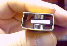
This version has another advantage. You can hold the small frame in your hands and move it back and forth on the aluminum strip, feeling the opposition of the forces to your motion.
Notice that in both these demos, the magnets align themselves to fall without touching the aluminum tube or strip. Why?
Slow rolling.
|
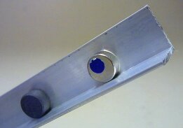
[May 2004] Someone asked me whether a rolling magnet on an aluminum sheet will be impeded by eddy currents. Surely such currents must be induced by a rolling magnet, but the geometry of the situation makes them relatively ineffective. However, here's a way to make a magnet roll slowly, using 1 inch angle aluminum stock (standard hardware store item in 8 ft lengths). The disk magnet (magnetized along its cyinder axis) rolls with one face close to one face of the aluminum. Advantage: only one magnet is needed. The photo shows a rare-earth magnet (with a blue sticker on its face for visibility), and also a similar size ceramic magnet (black). The ceramic magnet accelerates down the track without much opposition. The rare-earth magnet liesurely rolls with constant speed. Use of the comparison object convinces students that friction isn't responsible for slowing the magnet, since friction should be about the same in both cases. Ideally the comparison object should be completely non-magnetic, say aluminum or brass, machined to the same size as the magnet.
The aluminum angle stock may also be used as a track for spherical magnets.
A longer treatment of this demo is here: The slow fall.
Re: Answers left as exercise for the student. Send your answers to the address
shown at the right. The earliest
good one(s) which arrive may be posted here, with credit to author.
I will post (at my discretion)
answers which are in simple to explain, clear, correct, perceptive, and
which stimulate thinking and further discussion.
Posted answers, whether written
by me or by others, do not always
represent the final word on a given puzzle.
On several occasions perceptive readers have noticed things we missed,
or suggested simpler ways to explain something. So don't hesitate to
skeptically rethink given "answers".
![]()
Web sites with science experiments you can build yourself.
Web links to suppliers of physics toys and apparatus.
- Science Kits & Boreal Laboratories.
- Edmund Scientifics.
- Boreal Laboratories.
- Science Toys.
- Learning Technologies, Inc..
Return to Physics Demonstrations.
Return to Toys, Tricks and Teasers menu.
Return to Physics Documents.
Return to Donald Simanek's front page.