Mirror and Prism Methods
for 3d Macro Photography.
This page requires a monitor width of at least 1000 pixels in order to see both images for cross-eyed stereo viewing. Since the photos also have large vertical dimension, it helps to toggle the "full screen" view (F11 in Windows). However, if you haven't mastered that viewing method, these pictures may also be appreciated as 2d flat photos. All are © 2008 by Donald Simanek. For instructions on free-viewing 3d by the cross eyed method, see the How to View 3D page.
3d with first-surface mirrors.
An astounding variety of 3d systems use first-surface mirrors or prisms to achieve stereo with a single-lens 2d camera. I avoid mirrors for general picture-taking, because of the difficulty of keeping the delicate silvered mirror surfaces clean. But they are interesting systems just the same. So, having nothing better to do, I compiled this selection of the stereo systems that seem to me most practical, especially those suitable for use with digital cameras. My long term goal is to build every one of these and take stereo pictures with it, to better judge their practicality.Technically, optical systems that combine reflective surfaces and lenses are called catadioptric systems. In the fields of computer and robotic vision there's considerable interest in these because their inherent geometric limitations are often correctable by computer rectification of the captured images. Systems that are inherently self-rectifying, or nearly so, are sometimes possible, and are of most interest to 3d hobbyists like myself. Web searches for catadioptric stereo will yield considerable information on these.
Most of the devices described here were invented long ago and have been used since the earliest days of film photography. Some take on new interest because of the special properties of some digital cameras, such as shorter focal length lenses and smaller front diameters of lenses. The availability of digital software dedictated to stereo (like StereoPhotoMaker) makes it possible to easily overcome some of the geometric limitations of certain devices.
One caveat applies to any mirror stereo system used with an autofocus camera. These cameras often use a supplementary red or infrared light to aid in determining the subject distance. This may not be properly beamed to the subject by the mirrors, resulting in poor focus. Also, if using the camera's built-in supplementary flash, it, too, and its system for determining flash exposure, must be redirected to the subject being photographed. Each camera will require different ways to deal with this. This may not be easy to engineer.
One mirror, one lens, one camera.
 |
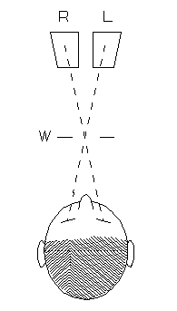
The logical order of presentation is to begin with one-mirror systems. The diagram to the left shows the principle. The real 2d camera is shown in black, its mirror image (virtual camera) is in red. These "two" cameras are separated by distance (b). The film or image sensor sees the subject on one side, its mirror image on the other side. The mirror image is reversed right to left and must be transposed later. Both images record the yellow region (A), while the green regions (B) and (C) are also recorded, but not in stereo, and this portion of the recorded picture is later cropped away and wasted. The horizontal angle of stereo coverage is considerably reduced. Larger mirror length (h) gives larger horizontal angle and/or allows larger stereo baseline (b).
With digital cameras we have the luxury of post-processing, so the mirror can be tilted as in the figure at the right, and the perspective distortion rectified later with StereoPhotoMaker software. So we can waste less of the sensor area. This is especially useful with small-baseline macro stereo.
In the diagram (above right) S is the subject being photographed, M is the mirror, L is the camera lens, L' is the image of the camera lens in the mirror. The trick is to place the mirror nearly perpendicular to the lens axis, tilted inward just a bit, so that the image of its far edge is near the center of the camera sensor. This works best if the camera lens' front element has small diameter. It happens that many digital cameras have small lenses. Here's a case where a wideangle camera lens is an advantage.
If your camera has a lens that moves in and out as it focuses, you must keep the near edge of the mirror far enough from the lens to avoid contact when the lens moves out.
The tilt of the mirror, required to capture a wider horizontal angle of view, necessarily produces convergence of the effective axes of the left and right pictures. This, combined with the fact that these axes are not normal to the sensor surface, results in keystone distortion of the reflected image. Back in the days of film photography this would have doomed this macro-stereo photography method to oblivion. But, as we will see, that kind of distortion of digital images can be "corrected" with computer software.
Details of the construction.
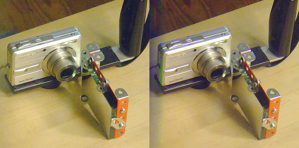
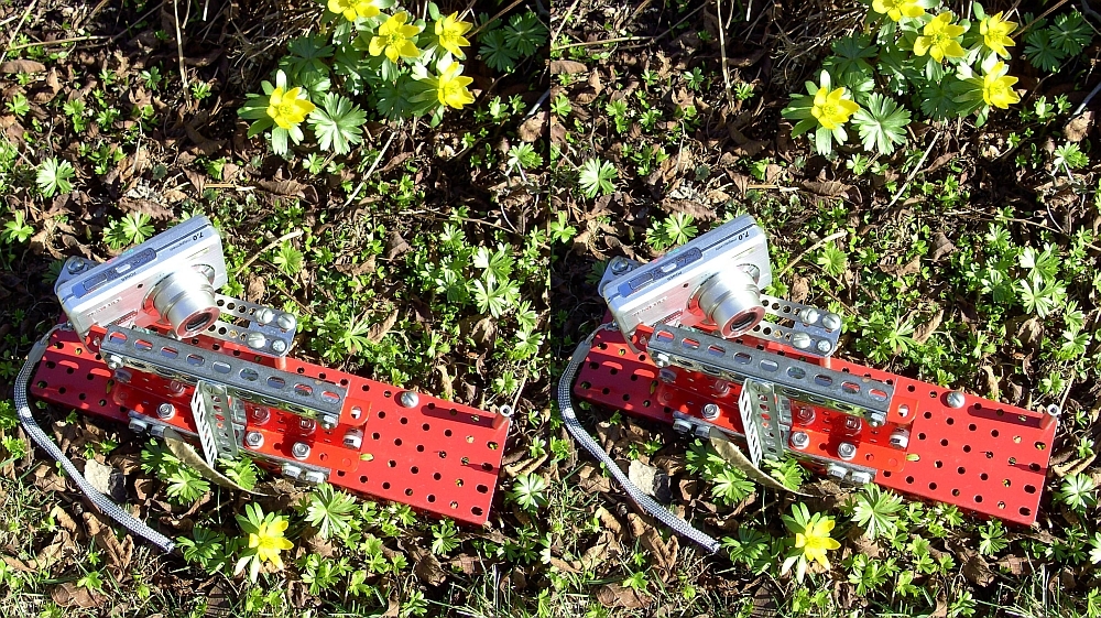
This prototype attachment is made of Erector and Meccano parts built upon an old flash adapter. The mirror is 2"x3". I've seen this method used with mirrors 8" or more in length.
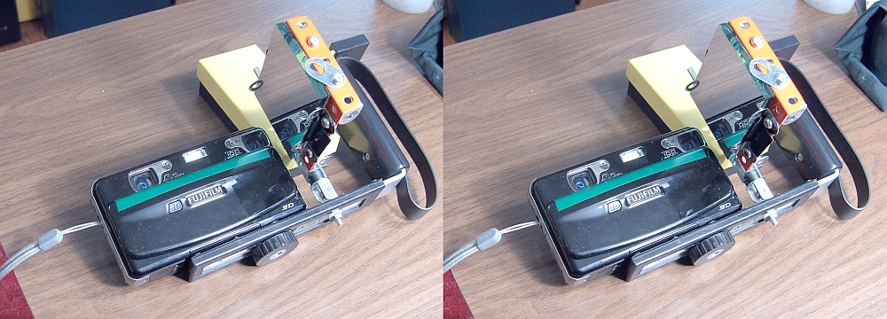
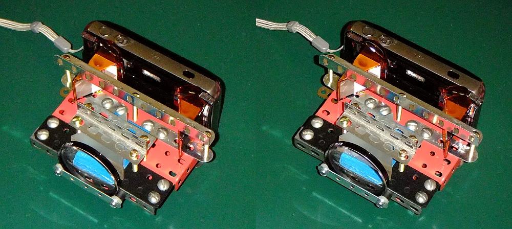
Since these one-mirror systems are the easiest to make, I constructed another prototype, using a Fuji 3d camera in its 2d mode. Notice that only the left lens of the stereo camera is used, the lens that functions in the camera's 2d mode. Also notice the lens' reflection in the mirror. The reflected image of the camera lens becomes effectively a second "virtual" lens. The two are less than an inch apart and tilted slightly, so their lens axes converge. This is a consequence of the necessity to tilt the mirror inward.
Of course the method can be used with various 2d cameras, especially the small "point and shoot" digital cameras. The Fuji has one advantage some others don't. The lenses are entirely within the camera, and do not move in and out from the camera front. So there's no possibility of the lens hitting the mirror.
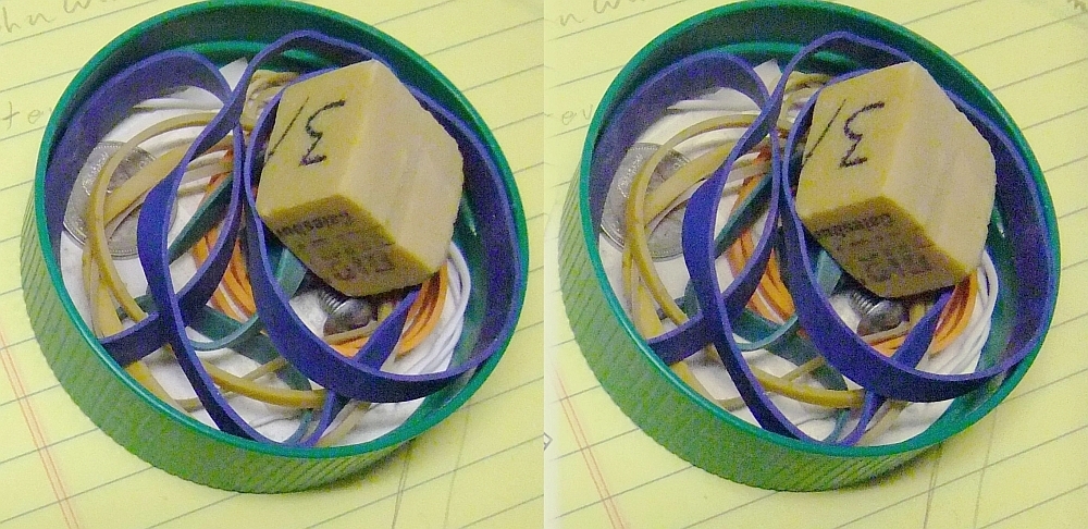
This photo was taken with this contraption. The subject is a 3 inch wide jar cap with rubber bands, an eraser and other junk inside. Note that the axis convergence exaggerates depth relative to width and height.
StereoPhotomaker (SPM) was used to process the pictures. SPM has a function that flips one image horizontally, but it works in a strange way, and I gave up trying to use it. So I imported the single JPG image and then saved the left and right images as separate files. With IrfanView image viewer I flipped the mirrored image horizontally. Then, again with SPM, I imported the left and right images and aligned and cropped them, saving them as a stereo pair for cross-viewing.
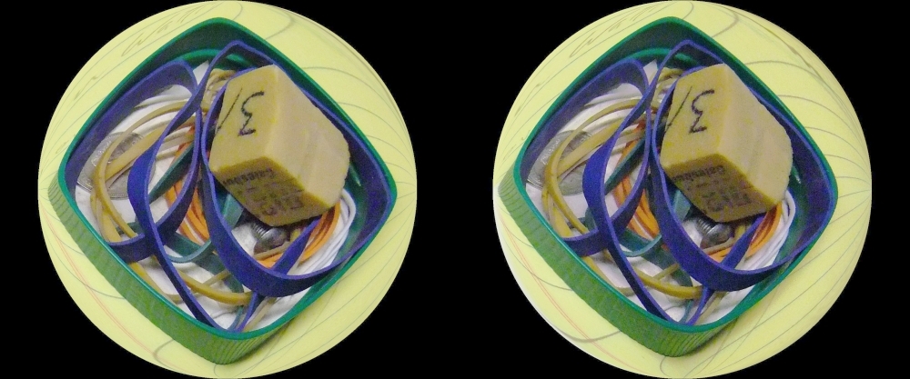
While fumbling around for the SPM functions, I found one that converts the images to spherical perspective (the "spherical distortion" function). Here's what happens when you use it. It's rather interesting, I think.
A lighter mirror could be used, and cut to a trapezoid shape to trim away unused portions of it. For some inspiration, see Hines Labs. Mirrors of that shape can be purchased. One of my correspondents likes stainless steel mirrors for experimentation.
The construction should be more rugged, and simpler. One immediate improvement would be to epoxy a metal anchor to the back of the mirror to hold the mirror in place and allow easy position and tilt adjustment in whatever support framework you design. Sylvan Weiller has taken some fine macro 3d pictures with a single mirror system. See Mirror Stereo. He presents them for parallel or cross eyed viewing as well as anaglyphs. Albrecht Kloeckner has a nice gallery of stereo macro photographs taken this way, with pictures of his simple home-built mirror holder.
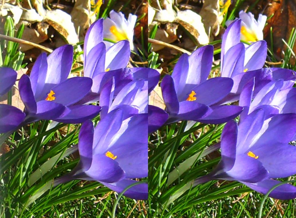
Simple as it is, this device is an excellent and inexpensive way to get into stereo macro photography, and the results can be quite satisfying. This picture of crocus and one bee was taken March 8, 2010, with a Traveler XS7 7mp 2d camera and a small (2"x 3") mirror, auto settings, handheld, no flash, and processed with SPM. The lens setting was "wide angle". The camera cost me $56 at an Aldi store a couple of years ago, and the front surface mirror can be bought for about $8.00.

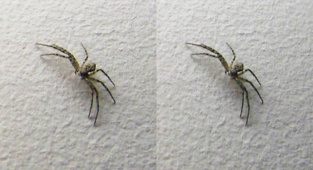
This friendly spider has been hanging around my workroom all winter, sometimes enjoying the warmth of my computer. His leg span is about 1/2 inch, so he was a good test of the one-mirror 3d adapter. This picture was hand-held with all camera settings automatic, and no flash. Illumination was a nearby fluorescent tube. The camera was only a 6 mp, and this picture was a small cropped portion of that.
Geometric distortion in stereo image-splitter devices.
|
Perspective disparity is present in any single lens device that splits the camera film or sensor area into L and R eye images side by side. It results from the fact that the light rays that form each image strike the sensor unsymmetrically in the L and R images. The rays to a point in the center of the picture are tilted with respect to the sensor's normal. So a photo of a rectangular window would image as a non-rectangular trapezoid. The distortion is in the opposite sense on the L and R images. This is a small effect, and may be considered of no importance for pictorial subjects that have no straight lines and no important details near the corners of the picture. But for precision scientific measurement, this requires computer rectification.
The geometry of the mirror stereo adapter itself may introduce additional distortion of this same kind, as can the stereo viewing method (cross-eye, particularly) that is used. Sometimes these can be contrived to somewhat offset each other.
Systems that rotate the images head to head or tail to tail have this distortion in the same sense, and therefore it usually isn't noticable in stereo viewing of pictorial subjects and needn't be corrected. For precision measurement work it still requires rectification.
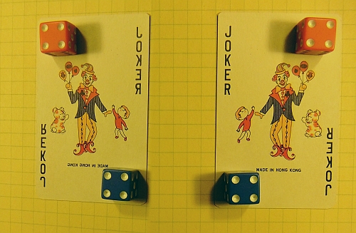
If you want to see this distortion in its worst case, photograph a playing-card lying on a piece of quadrille paper, aiming the camera straight down onto the paper. Use the widest angle setting your stereo device permits. Perspective disparity is worse with wide angles of view, and least with narrow angles. However, cross-eyed viewing of rather large images tends to compensate for this distortion by introducing the same kind of distortion in the opposite sense. Anyway, it's a wonder anyone gets comfortably viewable stereos with this method.
|
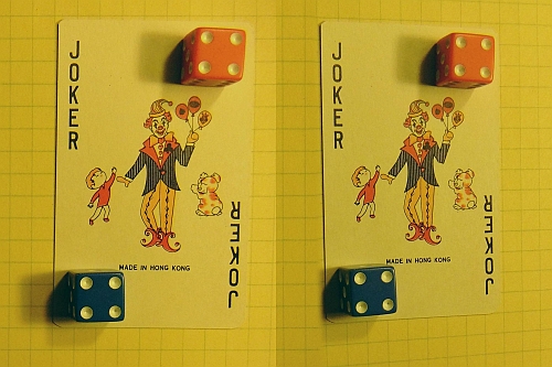
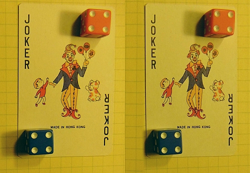
In this test we notice that the mirrored image is slightly darker, as expected, due to the mirror's light loss in reflection. SPM can easily balance this with its "auto color balance" function. I didn't do that here.
The final result still shows shear distortion of 3d space (in the dice), but for most subjects this is too small to notice. This kind of distortion warps rectangular solids into paralellopipeds. You can also see this effect on the rectangular eraser in the picture of the rubber bands above.
This kind of distortion can be eliminated by camera re-design. Loreo once marketed a film stereo camera that tilted the L and R film planes to compensate for it. Their newer LIAC stereo adapters for normal cameras accomplish some correction of this effect by clever mirror arrangments that interchange the left and right images on the film (or sensor).
Two mirrors, one lens, one camera.
Some websites have plans for stereo systems using two mirrors hinged together at their edges, making a small angle. The camera is aimed at the hinged edges. You can see a device of this kind at Tyrell Innovations. This site also discusses the perspective disparity such devices produce, and how this may be "corrected" with software. This sort of distortion, in the opposite sense, can also be produced by convergence of stereo axes in two-lensed stereo cameras. See a discussion of this at Keystoning / Convergence Error by Rick Wilson and John Bercovitz.The position and angle of the mirrors is important. It can affect (1) the virtual cameras' convergence, (2) the subject distance to the virtual lenses (both must be equal) and (3) the stereo interaxial. The following two figures schematically illustrate the possibilities.
|
Two mirrors M1 and M2 are hinged at H and make a small angle with each other. C is the camera and S is the subject being photographed. The dotted lines in the diagrams show the path of a ray from a centered subject to the center of its image in the camera. The hinged mirror device creates two "virtual" camera locations (V1 and V2) with displacement and convergence control. To control these two variables separately, one can unhinge the mirrors and displace them as shown in the second diagram. The mirrors still make a small angle with each other. If they were parallal, the virtual cameras would have diverging line of sight. The mirror angles also need to be adjusted so that the subject to virtual camera distances are equal, and this is why the lines of sight to the subject are both tilted compared to the previous diagram. Similar considerations apply to any device that uses two mirrors with small angle between them.
The far edge of M2 defines the dividing line between the L and R images on the film or sensor.
I have also built one of these for use with a 7 mp pocket digital camera, one with a telescoping lens. I was able to use the lens in its widest setting, with an effective stereo baseline of 1 inch and a subject distance of about six inches. The convergence of the virtual lenses is about 15 degrees. This seriously violates the 1:30 rule for stereo baseline:distance.
I'm told that this angled-mirror method was used way back in the days of daguerrotype photography in the 19th century. It goes back at least to Theodore Brown's "Stereoscopic Transmitter", patented in 1894, and described in his 1903 book Stereoscopic Phenomena of Light and Sight. Stereo photographers seldom use this method today. It takes some getting used to because the camera is aimed at right angles to the subject and both images are reversed left to right..
 | |
| Theodore Brown's Stereoscopic Transmitter, 1894. | Theodore brown's Stereophotoduplicon, 1894. |
|---|
Here's a prototype system constructed with two 2 inch wide mirrors and Meccano parts.
This picture of blue crocus was taken with it. Effective interocular is 3/4 inch. Auto-aligned with SPM.
Any system that has just one mirror reflection will flip the image left to right. This can be corrected in post-processing if it is not desired.
Two angled mirrors, one camera.
 |
 |
| The simple concept. | The camera recorded this. |
|---|
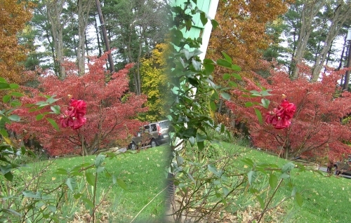
I made this prototype quickly, with a Traveler digital camera and two 2"x3" front surface mirrors. The camera was aimed down at the mirrors, which reflected the light from the forward image upward to the camera. The mirrors make a small angle to each other, so that the virtual lens positions are separated. The idea seems simple enough, but the diagram doesn't reveal that the mirror angle necessarily rotates both images, as the unprocessed image to the right shows.
Thanks to StereoPhotoMaker's "auto align" algorithm, the 12° rotation of each picture was easily corrected, but the necessary cropping was quite wasteful of pixels, and further reduced the angle of coverage.
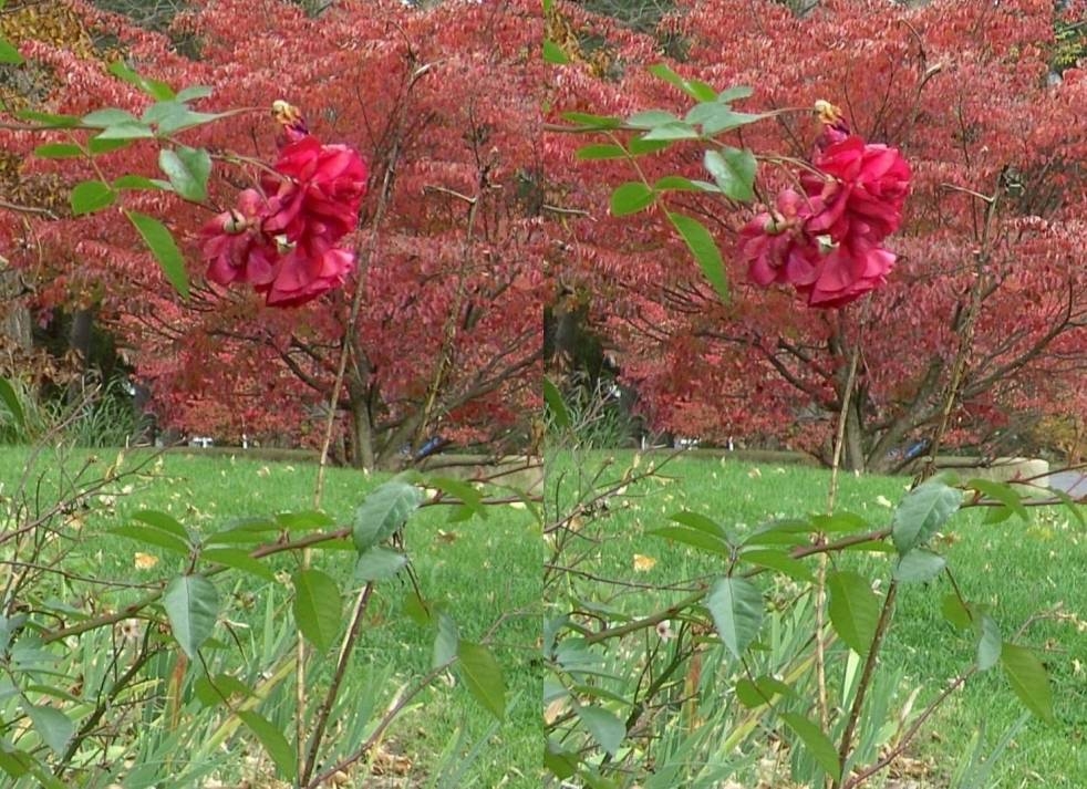
Taken on Oct 30, 2010, the stereo picture (below) could be called the "last rose of summer". The effective interlens stereo baseline was only 1.75 inches. The mirror width wouldn't permit more than 2 inches. 3"x4" mirrors would be better. StereoPhotoMaker's auto-align function is remarkably "smart" to cope with not only the 12° counter-rotation of each picture, but any skew distortion as well. These tilted mirror designs weren't used for stereo in the days of film photography because of the difficulty of correcting these geometric distortions.
Two angled mirrors, one plane mirror, one camera.
 |
| Practical angled-mirror 3d attachment. |
|---|
The basic idea of creating two virtual cameras with two mirrors at a slight angle can be implemented in many ways. By adding just one more mirror, you can modify the idea to reposition the subject in front of the camera.
The figure shows the evolution of the idea. In diagram A two mirrors M2 and M3 make a small angle of 1 or 2 degrees with each other. Mirror M1 is at 45° to the lens axis of the camera, and the other two mirrors are nearly the same angle. The virtual image of the camera lens formed by these two mirrors is shown by the dotted lines. If you draw a scale diagram of this you see a problem right away. The virtual lenses are separated, forming a stereo baseline, but they are at different distances from the subject. The result would be that the L and R stereo images are of different size, and there's a focus disparity as well. The central rays (to the center of each image) from the subject must be of the same length. This can be corrected, as in diagram B by angling the second two mirrors a bit to the right, until the virtual camera lenses lie in the same plane.
I have seen this idea implemented with the mirror components interchanged so that the two angled mirrors are nearest the camera lens. This has the disadvantage of making the dividing line between the pictures less sharply focused, creating a fuzzy boundary that must be cropped away. It also reduces the stereo axial separation, and is more suitable for macro photos at close distances, but less suitable for distant scenes.
Two angled mirrors, one plane mirror, one camera, symmetric arrangement.
 |
| Three mirror image splitter. |
|---|
Another practical angled-mirror system is shown here. It is like a two mirror periscope, with one mirror being made up of two mirrors making a small angle. But by placing the angled mirrors below the other one, this arrangement naturally equalizes the two distances from lens to subject, and is easier to adjust. This is just the previous design, but rotated 90°
This system could be used for "normal" 3d photography with a stereo baseline of 2.5 inches and parallel axes. With typical digital "point and shoot" cameras the "wide" lens setting has a horizontal coverage angle of 45°, so each picture of the L/R pair subtends an angle of 22.5°. Now with two mirrors of width 2.5", each at an angle of 5.6° to the camera lens axis (11.25° to each other) the parallel axis condition is achieved. This requires the two mirrors to be 5 inches from the camera lens. That's just barely achievable if you have a camera with protruding lens. Mirror M1 must be small and very near the camera lens.
The dividing line between the pictures on the film or sensor is the image of the joint between mirrors M2 and M3. In this system this fuzzy line is likely to be wider at one end. The mirror M1 nearest the lens L is simply a reflector, and may be smaller than the other two mirrors. This system has the advantage that the viewfinder shows the images right side up, and the subject is in front of the camera, where the camera's built in flash (if used) can illuminate it.
Although we have shown mirror M1 transparent for clarity, all the mirrors are front surface mirrors. For outdoor work, all mirrors should be in an enclosure. The enclosure should also shield the mirrors from the flash lamp.
 |
| Provisional patent US0042796. |
|---|
All macro 3d systems using slightly angled mirrors produce effective convergence of the virtual camera axes, and the unavoidable perspective distortion. Therefore they are mainly useful for macro photography with small interaxial distance using a digital camera and post processing with StereoPhotoMaker to correct this distortion.
In any case, you still have rotation of both images, so, in my opinion this isn't worth the extra trouble of adding a mirror and aligning everything properly.
Three mirrors, one lens, one camera.
Three mirror systems are very rare in the older literature of stereo. They have several problems: One is that one of the mirrors must be quite large relative to the camera. Also, since a three-mirror system is necessarily asymmetric, the mirror alignment and positioning are very critical, to ensure that both images are the same size. In principle you can completely avoid axis convergence due to the mirrors, but the perspective distortion due to the sensor/lens geometry is still present. Any other advantages these systems might have over other methods are not obvious to me. They clearly have application to scientific and technical photography, but probably would not be the first choice for amateur photographers doing pictorial photography.The one shown here is from a 1999 provisional US patent issued to Joshua M. Gluckman, and Shree K. Nayar of Columbia University. See their description, with picture: Rectified Catadioptric Stereo Sensors.
Four mirrors, one lens, one camera, tall format.
 |
| Conventional beamsplitter 3d attachment. |
|---|
Many beam-splitter adapters have been marketed that use mirrors or prisms and a single lens and camera. Few are still sold. Their reflective surfaces were arranged as a combination of two periscopes. They put the L and R images side by side on the film frame or sensor, each image taller than wide. The effective horizontal angle of view of the lens is halved. See this document by Fritz Waack for a discussion of the mathematics of these.
The figure at the right shows how the mirrors form two virtual images of the camera and its lens, their spacing being determined by the front mirror spacing. Sometimes the same adapater, or a similar one, is used with a slide projector and polarizers to project side by side stereo images superimposed on a metallic screen, using linear or circular polarization to separate the images.
|
This design was patented as the "Stereophotoduplicon" in 1894 by Theodore Brown, and described in his book Stereoscopic Phenomena of Light and Sight, The Gutenberg Press, Ltd, London 1903. (See picture earlier in this document.)
One can arrange the mirrors to interchange the pictures left and right on the film or sensor. The Loreo LIAC attachments do something like this.
Four mirrors, one lens, one camera, wide format.
Another kind of beam splitter rotates both pictures 90° and splits the film or sensor horizontally so that the images are wider than high. These include the Tri-Delta, and the newer TriDelta system from Tyrell Innovations. I have a separate document about this design: A home-built digital stereo camera using mirrors. Systems of this sort were used to photograph and project 3d movies in theaters in the 1970s. The advantage is that L and R images are one above the other on the same strip of film, and can't get out of alignment when projected. Also, any radial geometric distortion or illumination variation of the single lens is symmetrically balanced between the two images. This was a "widescreen" 3d format. These are sometimes called "over/under" 3d systems.
Two cameras, one half-silvered mirror.
 |
| Half-silvered mirror method. |
|---|
Here's a clever two-camera system for small-baseline stereo macro photography using one half-silvered mirror (reflects 50% and transmits 50% of the light). It is another old idea from the history of stereo. Ideally this requires two identical cameras. The effective stereo baseline can be adjusted by moving one of the cameras sidewise. So very small baseline separations are easily achieved. A matte black box is needed to suppress unwanted images, since both cameras see both a direct and a reflected image in such a mirror. Black plush cloth is good for making a non-reflective surface. If the subject is alive and moving, the camera shutters must be synchronized.
If your cameras don't autofocus at close distances you can use matched supplementary lenses on the two cameras. Better yet, use a close up lens between the half-silvered mirror and the subject. This may not be necessary with modern digital cameras that have macro autofocus capability. However, due to the slight sidewise disparity of the images, the cameras may not focus on the same spot of the subject, resulting in slight focus and exposure disparity. The exposure difference is easily corrected with software, the focus difference is usually so small that the eye/brain system compensates for it when viewing in 3d.
One great advantage of this system is that the effective stereo axes can be made perfectly parallel, for zero geometric distortion at all stereo base settings.
Stores that sell and cut glass usually also sell mirrors, and some even have partially silvered mirrors (for "one-way" mirrors). These can be useful and inexpensive for testing stereo adapter designs.
A custom version called the macrobox can be purchased from Ekeren 3d.
One stereo camera, one large lens.
 |
Probably the simplest way to use a stereo camera to do close-up photography is to use a single lens large enough to encompass both stereo lenses of the camera. In the 1950's stereo boom I used this with a Stereo Realist camera.
Such a large lens (at least 3.5 inches diameter) is heavy, not easily fit in a pocket. It produces stereo axis convergence which stretches the depth axis (z-axis) relative to the width and height axes (x and y axes) of the picture.
With a modern digital stereo camera, such as the Fuji 3d, you can take advantage of the camera's autofocus, and its 3x optical zoom. So you can move back from your subject and zoom in on it. With 3x, move 3 times further away. This effectively decreases the stereo interocular to 1/3 normal.
I have a separate web page about this: Telephoto 3d for close-up photography.
To minimize lens aberations it is best to have the lens surface of greatest curvature nearest the camera lenses. This is from the optician's "rule of thumb" that aberrations are least when the ray deviations are nearly the same size at both lens surfaces.

This stereo of Christmas candy illustrates typical results. Depth is exaggerated.
One stereo camera, four mirrors or prisms.
Now that we have at least one commercially made digital stereo camera (and perhaps more to come), some of the older ideas using mirrors and prisms can be adapted for macrophotography with such cameras. I have a separate web page showing one way to make a macro adapter for a standard stereo camera. See Macrophotography With the Fuji 3D Camera.
One stereo camera, three mirrors and a half-silvered mirror.
 |
| The supermacro, for very short baseline macro stereos. |
|---|
[Jan 15, 2010] I've not seen this design elsewhere, but it builds upon standard techniques used in reflective 3d adapters. The previous half-silvered mirror trick can be adapted to most any standard stereo camera, like the 50s film stereo cameras, or the digital Fuji 3d camera. While the half silvered mirror device above required two synchronized cameras, this one takes advantage of the fact that stereo cameras already are two cameras with synchronized functions.
The adapter requires a half silvered mirror and three front surface mirrors (or right angle prisms). C is the stereo camera, with lenses L and R. S is the subject. M designates front surface mirrors, and H is the half-silvered mirror. A black screen or box, B, prevents unwanted images. Sizes and placement of mirrors are tricky, and the path lengths from lens to subject must be exactly equal for both lenses. Therefore adjustment of the stereo baseline requires simultaneous adjustment of the two middle mirrors, a tricky mechanical problem to engineer. The "tele" setting of the camera lenses works best.
If the black screen, B, were not present, and a second subject were placed to the left of the half-silvered mirror, the two subjects would be superimposed, but one would be in "pseudostereo". If the lighting balance of the two subjects were adjusted so that the second image is fainter, a "ghostly" effect would be photographed, the mirror device acting like the Pepper's ghost stage illusion of the 19th century. Someone might find a use for this curiosity, but I can't.
For very small subjects, very close to the camera, you may need matched supplementary lenses in front of the camera lenses. Or, you could place just one supplementary lens in front of the half-silvered mirror, at the cost of introducing slight convergence of the stereo axes. Microscopists are accustomed to using convergence in their stereo work. Again, StereoPhotoMaker software can correct this.
This may seem an overkill design, but when you consider the advantage of having such short baseline stereo with autofocus, autoexposure, and automatic color balance, and perfectly synchronized shutters, you will have a system capable of photographing a gnat's eyelash in stereo, with a live gnat. (Slight exaggeration here.)
 |
| The simpler supermacro, for very short baseline macro stereos. |
|---|
Yet Another Stereo Macro Device.
The previous idea leads naturally to a simplification. Two mirrors and a half silvered mirror can be arranged as shown. One picture is reversed L/R, but that's easily fixed with StereoPhotoMaker. One drawback is the tricky adjustment to attain equal optical distance between subject and both camera lenses. If this is not done, the two images won't be the same size. This requires simultaneous adjustment of the half silvered mirror, H, and one of the front surface mirrors, M. It's probably best to adjust it once and not disturb it thereafter.
The versatile 30-60-90 prism.
In most of the devices described above prisms are used as reflectors only. But prisms also can be used to deviate light rays. Consider this interesting design for a 3d macro photography adapter.
 |
This uses two 30-60-90 degree prisms silvered on the longer leg of the right triangle, and an equilateral prism. You could substitute two 30-60-90 prisms for the equilateral prism.
Excellent quality 30-60-90 silvered glass prisms can be obtained at very little cost. Such prisms are in those eyeglasses that are sold for reading while lying down, or watching TV while lying down. Generally a pair costs $15 or less and you get two prisms.
How does this device compare to the one described above that uses four right angle prisms as reflectors? This one is a bit larger, and the useful angle of view is somewhat reduced. You'll have to crop the images more. Both systems require that the Fuji 3d camera be set on maximum optical telephoto (3X).
Here's a prototype made with the help of Erector and Meccano steel construction set parts, one pair of the TV glasses (earwpieces removed, left and right prisms cut apart at the nosepiece and rotated 90°) and one equilateral prism that just happened to be lying around waiting for a project.
For this prototype I retained the plastic frame from the TV glasses, since that provided a flange around each prism for easier mounting. Of course, it is best to enclose this entire device in a light proof black housing, and also provide a mount for close-up lenses in front of the large prism's front face.
The optical system interchanges left and right eye views, and flips each image left to right. This is easily corrected with IrfanView after processing with StereoPhotoMaker.
Sylvain Weiller had the clever idea of using the prisms from the inexpensive TV glasses. See his instructions and picture gallery.
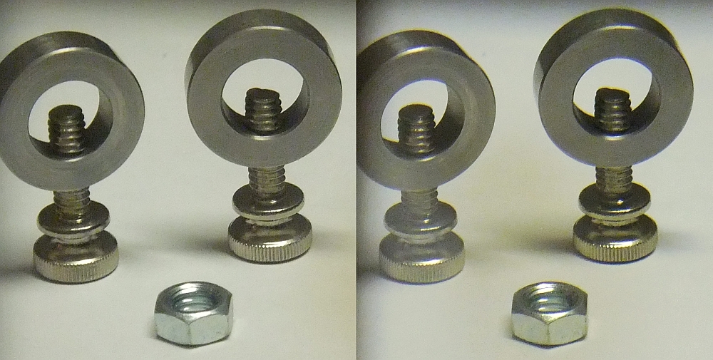
Here's a sample of the capabilities of this system, which is still in a mock-up prototype stage. The subject is two cylinder clamps for laboratory rods. They have outer diameter of exactly 1 inch. This is reversed, so the threads seem to be in the wrong sense.
Another design for very small interocular distances.
This is a variant of the mirror device described earlier. The half-silvered mirror R must be adjusted in position to obtain the desired effective interocular distance. Its reflective surface should be facing left, since the camera's focus and exposure control works through its left lens. A close up lens is useful. The entire unit must be inclosed in a light shield blackened in the inside. For initial testing, only the blackened shield, B, is necessary. The left lens of the Fuji 3d is the one the camera uses for focus and exposure control.
The Fuji 3d camera should be set on maximum optical telephoto (3X). The two pictures may have slight exposure difference, which can be corrected with StereoPhotoMaker. The two pictures will have slightly different size, but StereoPhotoMaker corrects for that also.
This design has real potential when used with a camera having smaller interlens spacing, like the Panasonic Lumix 3d camera with lenses spaced about one inch apart. This camera also has optical telephoto (4X).
More information.
John Wattie has a comprehensive list of stereo methods, to give you an idea what's possible. Unfortunately some of the links are dead. Also see his Stereoscopic Photography from New Zealand.
All photos on this page © 2008, 2018 by Donald E. Simanek.
More cross-eyed stereos in 3d Gallery One.
Still more cross-eyed stereos in 3d gallery Two.
Antique stereo view cards in 3d Gallery Three.
Building a digital stereo close-up photography system in 3d Gallery Four.
Review of the Loreo stereo attachment 3d Gallery Five.
Review of the Loreo macro adapter, 3d Gallery Five B
The Loreo stereo attachment—improved 3d Gallery Five C.
The Loreo LIAC attachment as a 3d macro device, 3d Gallery Five D.
Wildlife photography in your backyard, 3d Gallery Six.
A home-built digital stereo camera using mirrors 3d Gallery Seven.
Stereo close-up photography in your garden 3d Gallery Eight.
Stereo photography in your aquarium 3d Gallery Nine.
Stereo digital infrared photography 3d Gallery Ten.
Wider angle stereo with the Loreo LIAC 3d Gallery ll. A failed experiment.
Review of the Fuji FinePix Real 3D W1 camera 3d Gallery 12.
Macrophotography with the Fuji 3D camera. 3d Gallery13.
Panoramic stereo photography. 3d Gallery 14.
Tips for stereo photography with the Fuji 3d camera. 3d Gallery 15.
The Fuji 3d macro adapter with flash! 3d gallery 17.
Critters in stereo. 3d gallery 18
Wide angle stereo. 3d gallery 19.
Telephoto Stereo. 3d gallery 20.
2D to 3d Conversion. 3d gallery 21.
Stereos from outer space. 3d gallery 22.
Review of the Panasonic Lumix 3d digital camera. 3d gallery 23.
Reverberant flash for shadowless lighting.
Digital stereo photography tricks and effects.
Shifty methods for taking stereo pictures.
Guidelines for Stereo Composition.
![]()
Input and suggestions are welcome at the address shown to the right.
Return to the the 3d and illusions page.
Return to Donald Simanek's front page.